
Self-sealing gas incoming and release valve

A technology for exhaust valves and intake valves, applied in the direction of cleaning methods using gas flow, valve details, multi-way valves, etc., can solve problems such as incomplete fit, short life of seals, and leakage of explosive gases, and achieve Saving use and maintenance costs, good sealing reliability, and enhanced safety effects

Pending Publication Date: 2020-04-21
南京智必达自动化科技有限公司
View PDF0 Cites 0 Cited by
  • Summary
  • Abstract
  • Description
  • Claims
  • Application Information

AI Technical Summary

Problems solved by technology

[0003] The air intake system of the existing thermal energy deburring machine is compressed and sealed from the outside to the inside by the seal, and it is completely compressed by external power (hydraulic, pneumatic, mechanical, etc.), because any compression mechanism has elastic deformation, resulting in In the case of high impact, it cannot be fully fitted, and the seal fails. Although this failure occurs only at the moment of impact, the seal is slightly ablated due to the instant failure, but as time accumulates, the life of the seal will decrease. Very short, generally about 5000 times
The machine beats about 30S each time, so the seal is replaced about once a week, which is very cumbersome
The most important thing is that if the holder is damaged during the combustion and explosion of the equipment, the seal will fail, and the valve core will open accidentally. This opening will cause high temperature and high pressure explosion gas to leak out, resulting in a fatal safety accident

Method used


Image

  • Self-sealing gas incoming and release valve
  • Self-sealing gas incoming and release valve
  • Self-sealing gas incoming and release valve

Examples


Embodiment 1

[0017] The technical solution of the present invention will be further described in detail below in conjunction with the accompanying drawings.

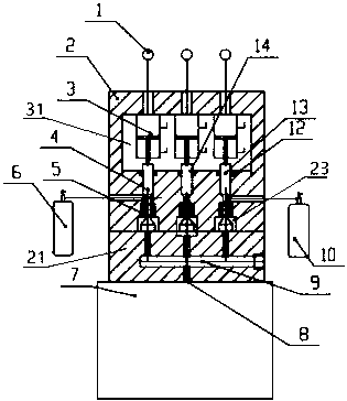
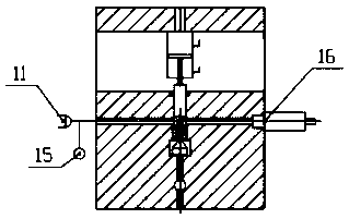
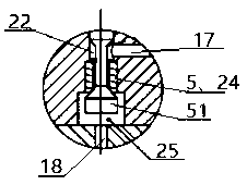
[0018] The self-sealing gas intake and exhaust valve is mainly composed of an intake valve body 2 and a working valve body 21. The air intake valve body and the working valve body are a sealed and detachable structure. The intake valve body includes a gas valve core 4 and an oxygen valve. Core 13, exhaust valve core 14 and the clamp 3 of each valve core, and the supporting valve seat 5 and seal 12 of each valve core, one end of the valve core is connected to the suppressor 51 provided by the inverted conical round table, and each clamps The device provides the working power of the clamp through the external power source 1, and the valve core movement hole 22 for the valve core to move in and out is arranged in the intake valve body, and the valve core movement hole divides the intake valve body into an intake working chamber 31 and a ...


PUM


Abstract

The invention discloses a self-sealing gas incoming and release valve. The valve comprises a gas incoming valve body and a working valve body connected with the gas incoming valve body; the gas incoming valve body is provided with a gas channel communicated with the outside; the working valve body is provided with a mixing channel communicated with a combustion chamber; and the air incoming valvebody comprises an air incoming working cavity, a restraining cavity and valve element movement holes, wherein the air incoming working cavity, the restraining cavity and the valve element movement holes are formed in the air incoming valve body; the air incoming working cavity and the restraining cavity are formed on two sides of the valve element movement holes respectively. Structurally, a valvecore and a valve seat are designed into an inverted cone form; when explosion combustion is performed in the combustion chamber, gas pressure in the combustion chamber is instantaneously increased; the increased pressure enables the suppressor of the valve core to be pressed on the valve seat more tightly, the larger the explosion pressure is, the more reliably the valve core is pressed to the valve seat; and even if a clamper breaks down, sealing failure can be avoided. Therefore, reliable sealing is realized; the failure rate of equipment is low; the service life of a sealing piece is longer; use and maintenance cost is saved; and the safety of the equipment is enhanced.

Description

technical field [0001] The invention relates to an intake and exhaust system, in particular to an intake and exhaust valve applied to a thermal energy deburring machine tool. Background technique [0002] The thermal energy deburring machine tool uses gas and oxygen to ignite and explode in the combustion chamber, and uses the high temperature and high pressure during the explosion to remove the burrs of the workpiece in the combustion chamber. The gas needs to be evenly mixed in proportion to ensure reliable combustion and ignition; when ignited, burned and exploded, it will generate an average guaranteed pressure of 20 times the inflation pressure and an impact pressure of 20-100 times. This requires that the intake and exhaust systems must be well sealed, otherwise it will cause the leakage of explosive gas, which may cause damage to the equipment, or cause major safety accidents. At the same time, the burned gas is discharged to the outside through the system, because a...

Claims


Application Information

Patent Timeline
Patent Type & Authority Applications(China)
IPC IPC(8): F16K11/044F16K27/02B08B5/02
CPCF16K11/044F16K27/0263B08B5/02
Inventor 程治杰唐郭胡伟
Owner 南京智必达自动化科技有限公司
Learn More