
Over-temperature steam detection control method of steam box

A technology for detection and control of steam, applied in the direction of timing control of ignition mechanism, steam cooking utensils, cooking utensils, etc., can solve the problems of low utilization rate of water in a pot, poor control of steam discharge, easy to cause water accumulation, etc., to avoid thermal efficiency. Waste, reduced water accumulation, high thermal efficiency

Active Publication Date: 2020-04-21
NINGBO FOTILE KITCHEN WARE CO LTD
View PDF15 Cites 8 Cited by
  • Summary
  • Abstract
  • Description
  • Claims
  • Application Information

AI Technical Summary

Problems solved by technology

[0004] The overheated steam detection and control methods mentioned in the above patents are to achieve overheated steam by reheating the steam by the high temperature steam generator itself or by controlling the reheated steam of the steam generator and the external overheating device to achieve overheating. Steam, however, both of these methods require the steam generator to continuously generate a large amount of steam, which can be realized through secondary heating. To maintain superheated steam, the water in the steam generator must be heated all the time to generate new steam. The overheated steam can only be generated through external secondary heating, which will cause low thermal efficiency; in addition, in the heating process, the overheated steam needs more water, and the utilization rate of a pot of water is not high, and there is a waste problem; moreover, the above patent The heating method in the medium will cause poor control of steam emission, which will easily lead to water accumulation

Method used


Image

  • Over-temperature steam detection control method of steam box

Examples


Embodiment Construction

[0028] The present invention will be further described in detail below in conjunction with the accompanying drawings and embodiments.

[0029] This embodiment discloses a steam box, the steam box includes a main control unit, a water inlet unit, a steam generator capable of inputting steam to the inner tank of the steamer box, a top heating film located on the inner tank, and a temperature control device for the inner tank. The measured inner tank temperature detection unit also includes a back heater installed in the inner tank, a back heating tube, a bottom heating plate and a bottom temperature sensor specially detecting the bottom temperature of the inner tank; the basic structure of the steamer is the existing Technology, what distinguishes the existing technology in this application is that the back heater located on the back of the inner tank, the back heating pipe, the bottom heating plate located at the bottom of the inner tank and the bottom specially detecting the te...


PUM


Abstract

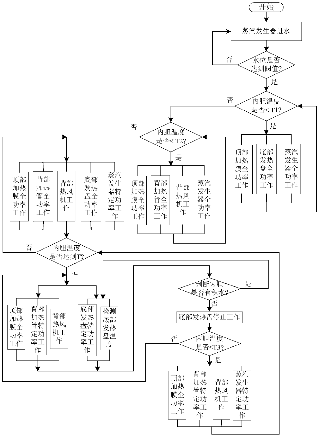
An over-temperature steam detection control method of a steam box is characterized by comprising the following steps: 1, feeding water; 2, judging whether the water level is reached; 3, judging whether the temperature is lower than T1 or not; 4, allowing a top heating film, a bottom heating disc and a steam generator to work in a full-power mode; 5, judging whether the temperature is lower than T2or not; 6, allowing the top heating film, the bottom heating disc and the steam generator to work in a full-power mode; 7, allowing the top heating film, a back heating pipe and the bottom heating disc to work at full power, and allowing the steam generator to work at specific power; 8, judging whether the temperature reaches T or not; 9, stopping the steam generator, and detecting the bottom temperature; 10, judging whether water is accumulated or not; 11, allowing the bottom heating disc to work at a specific power; 12, judging whether the temperature is less than or equal to T3; and 13, allowing the top heating film to work at full power, and the back heating pipe and the bottom heating disc to work at a specific power. The over-temperature steam detection control method has the advantages that heating elements are additionally arranged to conduct secondary heating on steam, different temperature intervals are set to control different heating devices respectively, the heat efficiency is higher, and accumulated water in a cavity is effectively reduced.

Description

technical field [0001] The invention relates to a high-temperature steamer, in particular to a method for detecting and controlling overheated steam of the steamer. Background technique [0002] High-temperature steamer, also known as over-temperature steamer, refers to a steamer that uses steam over 100°C to steam food. Over-temperature steam can penetrate food more easily, making difficult-to-cook food easier to cook, and shortening the cooking time by more than 20%. , retain food nutrition, improve food taste. The high-temperature steamer usually has a built-in double steam generator, and through the back steam generator and the overheating device at the bottom, the water vapor becomes 110°C high-temperature steam. [0003] In the prior art, the detection and control of the overheated steam by the steamer is often adopted, such as the existing Chinese utility model "A High-temperature Steam Generator and Electric Steamer" with the application number CN201820500985.8 and ...

Claims


Application Information

Patent Timeline
Patent Type & Authority Applications(China)
IPC IPC(8): A47J36/32A47J27/04A47J27/16A23L5/10
CPCA47J36/32A47J27/04A47J27/16A23L5/13A47J2027/043
Inventor 王玉鹏王伟方献良
Owner NINGBO FOTILE KITCHEN WARE CO LTD
Learn More