Refrigeration cycle device
A refrigeration cycle and refrigerant technology, applied in refrigerators, refrigeration components, refrigeration and liquefaction, etc., can solve the problems of complex switching control, complex circuit structure, etc.
- Summary
- Abstract
- Description
- Claims
- Application Information
AI Technical Summary
Problems solved by technology
Method used
Image

Examples
no. 1 approach
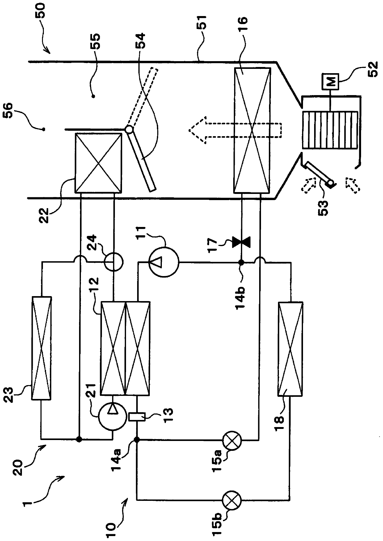
[0054] First, refer to Figure 1 ~ Figure 3 A first embodiment of the present invention will be described. The refrigeration cycle device 10 of the first embodiment is applied to a vehicle air conditioner 1 mounted on an electric vehicle that obtains driving force for vehicle running from a running motor.
[0055] In the vehicle air conditioner 1 , the refrigeration cycle device 10 functions to adjust the temperature of the blown air blown into the vehicle interior, which is a space to be air-conditioned. This blown air corresponds to the heat exchange object fluid in this invention.
[0056]In addition, the vehicle air conditioner 1 can realize a plurality of operation modes by switching the refrigerant circuit according to the operation mode. The plurality of operation modes include a cooling mode, a heating mode, a dehumidification and heating mode, and the like.
[0057] The cooling mode is an operation mode for cooling the blown air to cool the vehicle interior, and is...
no. 2 approach
[0184] Next, refer to Figure 4 A second embodiment different from the first embodiment described above will be described. In addition, in Figure 4 In , the same reference numerals are attached to the same or corresponding parts as those of the first embodiment. This also applies to the following drawings.
[0185] Similar to the first embodiment, the refrigeration cycle device 10 of the second embodiment is applied to a vehicle air conditioner 1 mounted on an electric vehicle, and functions to adjust the temperature of blown air blown into the vehicle interior as a space to be air-conditioned.
[0186] Such as Figure 4 As shown, the vehicle air conditioner 1 of the second embodiment includes a refrigeration cycle device 10 , a high-temperature-side heat medium circuit 20 , and an indoor air-conditioning unit 50 as in the first embodiment.
[0187] The structures of the high-temperature-side heat medium circuit 20 and the indoor air-conditioning unit 50 in the second emb...
no. 3 approach
[0265] Next, refer to Figure 6 A third embodiment different from the above-described embodiments will be described. The refrigeration cycle device 10 of the third embodiment is applied to the vehicle air conditioner 1 mounted on an electric vehicle as in the above-mentioned embodiments, and functions to adjust the temperature of the blown air blown into the vehicle interior as a space to be air-conditioned.
[0266] Such as Figure 6 As shown, in the vehicle air conditioner 1 of the third embodiment, the high temperature side water-refrigerant heat exchanger 12, the high temperature side heat medium circuit 20, etc. The exchanger 12b serves as a heating unit.
[0267] Therefore, in the third embodiment, the indoor condenser 12a and the outdoor heat exchanger 12b function as the heating unit in the present invention. The structure of the third embodiment is basically the same as that of the first embodiment except this point.
[0268] An indoor condenser 12a is connected t...
PUM
 Abstract
Description
Claims
Application Information
 - R&D
- Intellectual Property
- Life Sciences
- Materials
- Tech Scout
- Unparalleled Data Quality
- Higher Quality Content
- 60% Fewer Hallucinations
Browse by: Latest US Patents, China's latest patents, Technical Efficacy Thesaurus, Application Domain, Technology Topic, Popular Technical Reports.
© 2025 PatSnap. All rights reserved.Legal|Privacy policy|Modern Slavery Act Transparency Statement|Sitemap|About US| Contact US: help@patsnap.com