multi-axis drive
A technology of a driving device and a switching device, which is applied to the deceleration device of a DC motor, a conversion device of output power, and the control of an AC motor, etc., can solve the problems of high cost, complexity, and inability to realize the miniaturization of the device.
- Summary
- Abstract
- Description
- Claims
- Application Information
AI Technical Summary
Problems solved by technology
Method used
Image

Examples
Embodiment approach 1
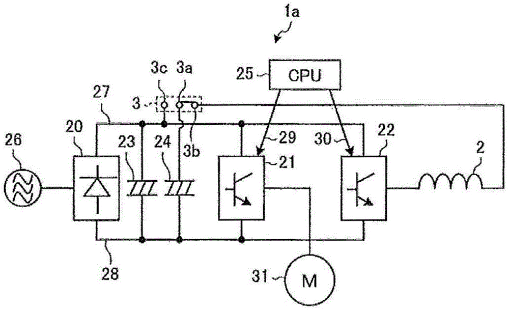
[0035] figure 1 It is a block diagram showing the configuration of the multi-axis drive device according to Embodiment 1 of the present invention. In the first embodiment and the five embodiments described later, an application example to a multi-axis drive device having a structure capable of driving two motors is shown for easy understanding.
[0036] First, for ease of understanding, refer to figure 1 , a multi-axis driving device having a structure capable of driving two motors will be briefly described. That is, in figure 1 Among them, a multi-axis driving device having a structure capable of driving two motors generally includes: a converter circuit 20 ; inverter circuits 21 and 22 ; bus voltage smoothing capacitors 23 and 24 ; and a control unit 25 .
[0037] The converter circuit 20 is a full-wave rectification circuit composed of a diode bridge, and converts a commercial AC power supply 26 into a DC power supply. The inverter circuits 21 and 22 are arranged in par...
Embodiment approach 2
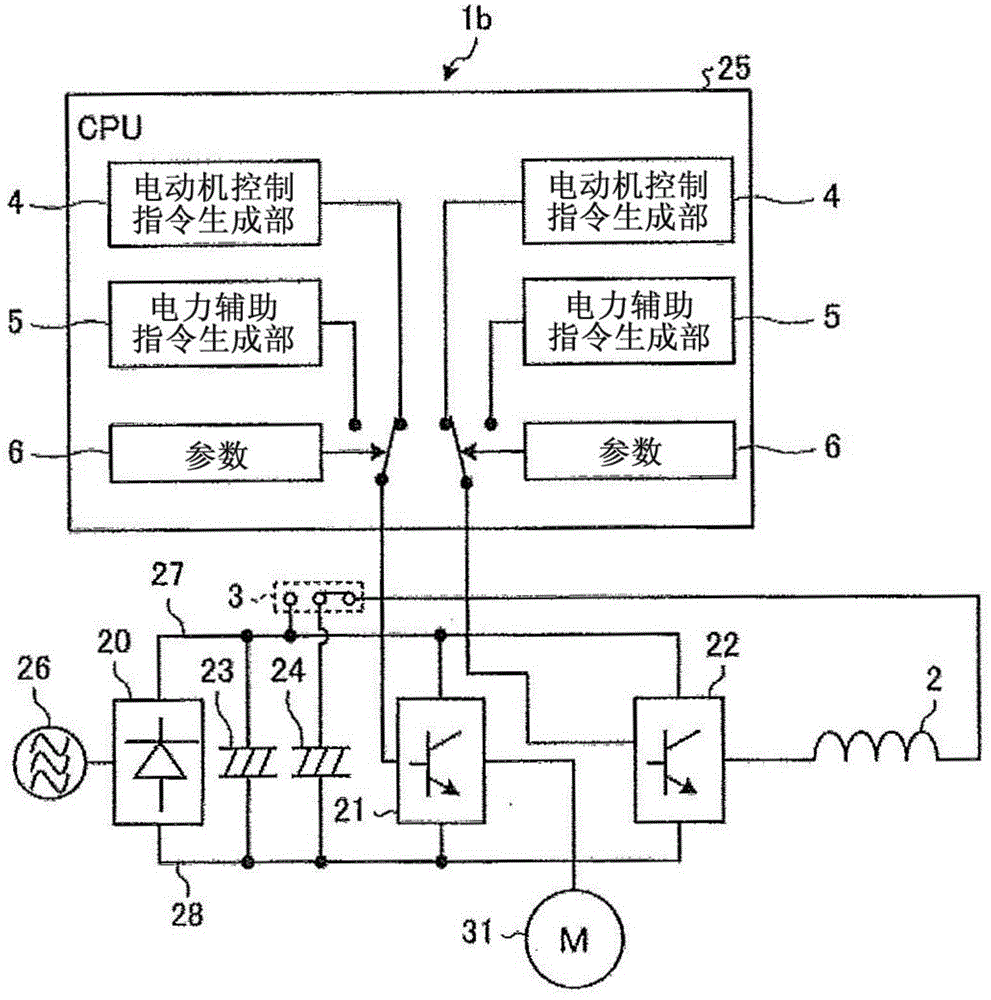
[0049] figure 2 It is a block diagram showing the configuration of the multi-axis drive device according to Embodiment 2 of the present invention. In addition, in figure 2 in, right with figure 1 The same or equivalent structural elements shown in (Embodiment 1) are denoted by the same reference numerals. Here, the description will focus on the part related to the second embodiment.
[0050] exist figure 2 In the multi-axis driving device 1b according to the second embodiment, in figure 1 The specific configuration content of the control unit 25 is shown in addition to the configuration shown in (Embodiment 1). Other structures of the multi-axis driving device 1b and figure 1 The structure of the multi-axis drive device 1a is the same.
[0051] That is, the control unit 25 is provided with a motor control command generation unit 4 , an electric power assist command generation unit 5 , and a parameter 6 for each inverter circuit. exist figure 2 In , since there are...
Embodiment approach 3
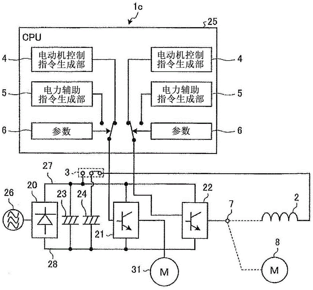
[0057] image 3 It is a block diagram showing the configuration of the multi-axis drive device according to Embodiment 3 of the present invention. In addition, in image 3 in, right with figure 2 The same or equivalent structural elements shown in (Embodiment 2) are denoted by the same reference numerals. Here, the description will focus on the parts related to Embodiment 3. FIG.
[0058] exist image 3 Among them, in the multi-axis drive device 1c according to the third embodiment, in figure 2 In the configuration shown in (Embodiment 2), the output terminal of the inverter circuit 22 is switchably connected to one end of the reactor 2 and the motor 8 via the switching device 7 that does not depend on electric signals.
[0059] The switching device 7 that does not depend on electric signals is a terminal block or a connector, and has a structure that one end of the reactor 2 and the motor 8 are switched and connected to the switching device 7 by manual work, so that th...
PUM
 Abstract
Description
Claims
Application Information
 - R&D
- Intellectual Property
- Life Sciences
- Materials
- Tech Scout
- Unparalleled Data Quality
- Higher Quality Content
- 60% Fewer Hallucinations
Browse by: Latest US Patents, China's latest patents, Technical Efficacy Thesaurus, Application Domain, Technology Topic, Popular Technical Reports.
© 2025 PatSnap. All rights reserved.Legal|Privacy policy|Modern Slavery Act Transparency Statement|Sitemap|About US| Contact US: help@patsnap.com