
Wireless sleep control system and method

A technology of control system and control method, applied in the direction of wireless communication, advanced technology, power management, etc., can solve the problems that are not suitable for large-scale distributed network monitoring system, distinction, single sleep control method, etc.

Active Publication Date: 2020-04-17
北京必创科技股份有限公司
View PDF10 Cites 8 Cited by
  • Summary
  • Abstract
  • Description
  • Claims
  • Application Information

AI Technical Summary

Problems solved by technology

[0006] Second, when the monitored equipment is running or stopped, the data collected by the sensor cannot be distinguished from the data when the monitored equipment is faulty. For example, when the ship is sailing or stopping, the lighting system on the ship is always on. , so the torque value of the shaft in the lighting power system does not actually change. However, when the ship stops, the torque of the shaft in the lighting power system does not need to be monitored. In this application scenario, the battery-powered wireless The torque monitoring sensor will no longer be suitable for judging whether it needs to go to sleep through the data collected by itself
[0007] Although, in many monitoring systems, related technologies involve triggering by external equipment (such as the Chinese patent application document with publication number CN109040583A) to make battery-powered equipment dormant, this method is not suitable for large-scale distribution network monitoring system
[0008] To sum up, the existing wireless device sleep control method is single, and it cannot realize the sleep wake-up management of wireless devices in the networked monitoring system, such as wireless sensors, for different situations.

Method used


Image

  • Wireless sleep control system and method
  • Wireless sleep control system and method
  • Wireless sleep control system and method

Examples


Embodiment 1

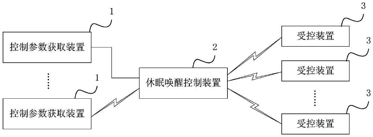
[0211] Such as image 3 As shown, in this embodiment, the gateway is composed of a first energy unit, an input interface, an output interface, a first data processing unit, a first wireless communication unit and a first antenna. Wherein, the first energy unit provides power for the entire gateway, and the input interface is an interface for transmitting information of external devices to the gateway through a wired method, and the external devices include wired devices. The output interface is an interface through which the gateway communicates with external equipment, and the gateway uses the output interface to transmit data to the external equipment, and the external equipment includes a monitoring host. The first data processing unit is mainly used to package the input data and forward it to the monitoring host. At the same time, the gateway is used as a dormant wake-up control device to realize the management and control of the trigger device (ie, the control parameter a...

Embodiment 2

[0233] The hardware structure of this embodiment is completely the same as that of Embodiment 1. When the first wake-up unit of the gateway and the second wake-up unit of the wireless device exchange information, there are two ways: active and passive. In this embodiment, a passive mode is adopted, that is, when the gateway determines that the wake-up information meets the wake-up condition, the first wake-up unit of the gateway sends an interactive command in time to establish a connection with the second wake-up unit of the wireless device and sends the wake-up command to the wireless device Wake-up unit. After the wireless device wake-up unit receives the wake-up instruction sent by the gateway, it immediately triggers the wireless device to wake up the wireless device and start working. After the gateway receives the normal operation instruction of the wireless device, it immediately turns off the first wake-up unit of the gateway. At the same time, After the wireless devi...

Embodiment 3

[0240] Figure 7 , Figure 8 The structures of the gateway and the wireless device in Embodiment 3 are shown respectively. The hardware structure of this embodiment is identical to that of Embodiment 1 except for the first antenna and the second antenna. In this embodiment, both the first antenna and the second antenna are broadband antennas, that is, the first antenna is replaced with the first broadband antenna, and the second antenna is replaced with the second broadband antenna.

[0241] The wireless communication module used for normal working data transmission in the wireless device and the gateway is the same as the wake-up unit used for wake-up command interaction. However, the antenna of the wireless communication module adopts a wide-band antenna. Frequency, when the wireless device wakes up the unit to work after sleep, the wake-up frequency is used. The working frequency is different from the wake-up frequency. Usually, the wake-up frequency is low frequency, and...


PUM


Abstract

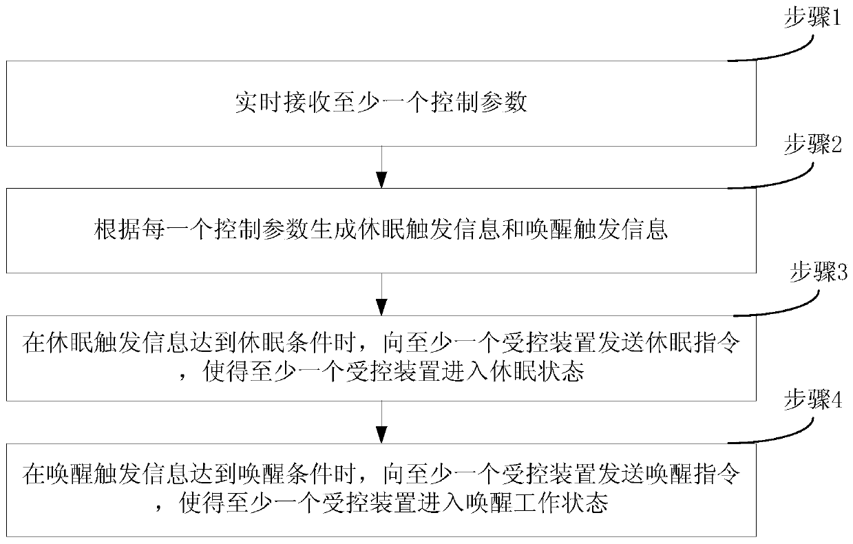
The invention discloses a wireless sleep control system and method. The system comprises a control parameter acquisition device, a sleep wake-up control device and a controlled device. According to the invention, the method comprises the steps: enabling the control parameter acquisition device to acquire control parameters; enabling the sleep wake-up control device to generate dormancy triggeringinformation and wake-up triggering information according to the control parameters; determining whether a sleep condition or a wake-up condition is met or not by judging the sleep triggering information and the wake-up triggering information; when the sleep condition or the wake-up condition is met, sending a sleep instruction or a wake-up instruction to a controlled device to enable the controlled device to enter a sleep or wake-up working state. According to the invention, the purpose of controlling the other part of wireless sensors powered by the battery to sleep and wake up by utilizing monitoring data of one part of sensors can be realized, and the method is particularly suitable for application scenes needing long-term sleep.

Description

technical field [0001] The invention relates to the technical field of wireless monitoring, in particular to a wireless sleep control system and method for controlling wireless devices, especially wireless sensors, to enter long-term sleep and wake up. Background technique [0002] The structure of the traditional large-scale equipment status monitoring system adopts a two-level structure, that is, it is composed of a status monitoring device and a monitoring host. The status monitoring device and the monitoring host use a wired connection. The status monitoring device, such as a sensor, is used to collect status information. For example, the wind force, wind direction, attitude, etc. of the ship during navigation, the stress, inclination, ambient temperature, humidity, etc. of the mechanical arm of the large coal shearer when mining coal underground, these status information are directly transmitted to the monitoring host through the cable. With the development and applicat...

Claims


Application Information

Patent Timeline
Patent Type & Authority Applications(China)
IPC IPC(8): H04W52/02
CPCH04W52/0225Y02D30/70
Inventor 陈得民
Owner 北京必创科技股份有限公司
Learn More