
Traction device for cable laying of power supply company

A cable laying and pulling device technology, applied to cable laying equipment and other directions, can solve the problems of labor consumption, difficulty, large cable diameter and weight, etc., and achieve the effects of convenient use, wide use range and manpower saving.

Active Publication Date: 2020-04-17
STATE GRID CORP OF CHINA +1
View PDF17 Cites 3 Cited by
  • Summary
  • Abstract
  • Description
  • Claims
  • Application Information

AI Technical Summary

Problems solved by technology

[0002] Cable laying is a process that is often involved in the process of electric power construction. The general method is to support the cable shaft on the ground, and then manually pull the end of the cable to drive the cable to lay. Pulling by many people is labor-intensive; when the cable needs to pass through the pipe, the general method is to first pass the rope through the pipe, tie one end to the cable, and pull the other end to realize the cable passing through the pipe, but this method has limitations , if the pipe is too long, there is a bend, or the cable has a large diameter and weight, it will be very difficult to use manpower to pull the cable through the pipe, and the long-distance cable laying cannot be completed, and many problems will arise during the pulling process

Method used


Image

  • Traction device for cable laying of power supply company
  • Traction device for cable laying of power supply company
  • Traction device for cable laying of power supply company

Examples


Embodiment Construction

[0023] The following will clearly and completely describe the technical solutions in the embodiments of the present invention with reference to the accompanying drawings in the embodiments of the present invention. Obviously, the described embodiments are only some, not all, embodiments of the present invention. Based on the embodiments of the present invention, all other embodiments obtained by persons of ordinary skill in the art without making creative efforts belong to the protection scope of the present invention.

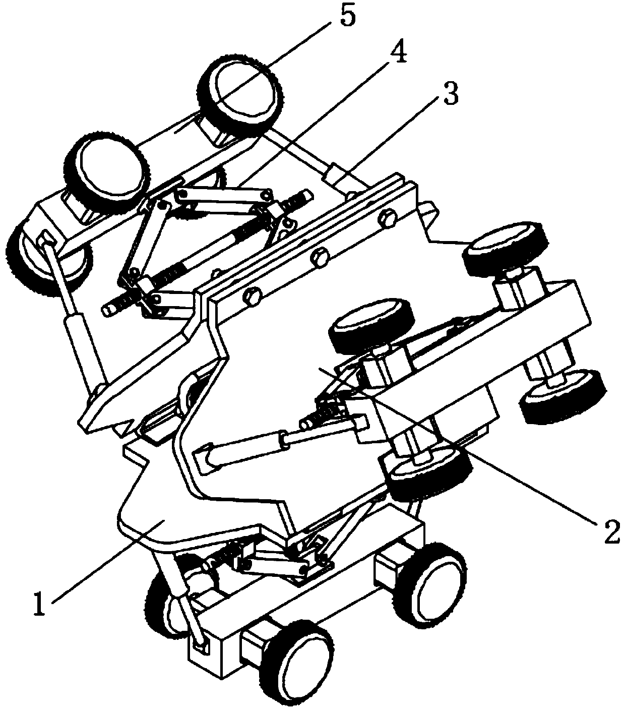
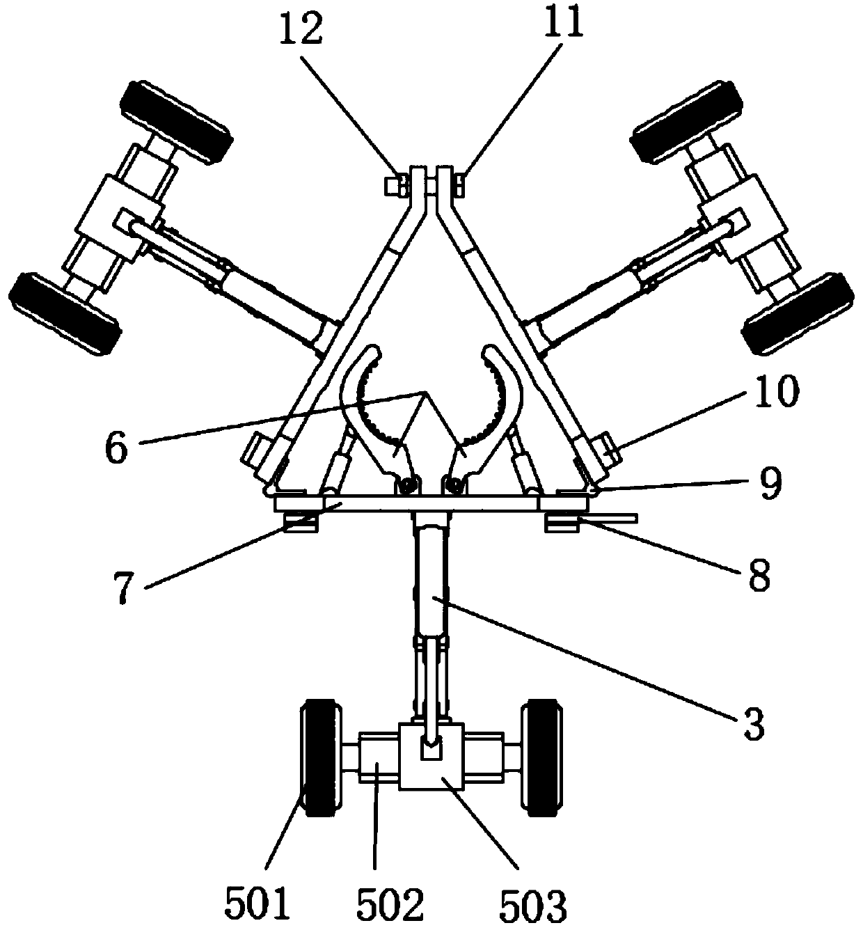
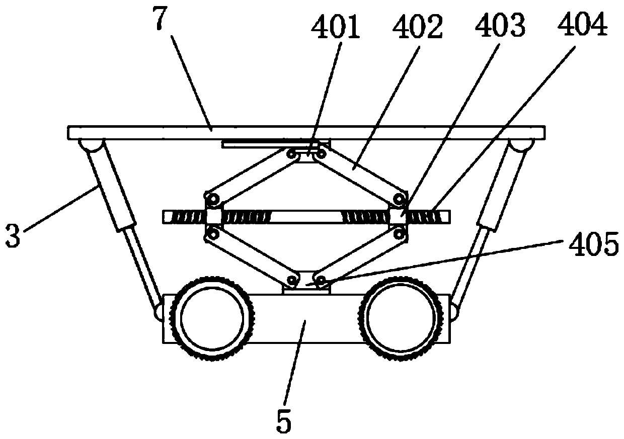
[0024] see Figure 1-5 , the present invention provides a technical solution: a traction device for cable laying of a power supply company, comprising a main traveling unit 1 and two groups of auxiliary traveling units 2 hinged with the main traveling unit 1, and the two groups of auxiliary traveling units 2 are connected to each other through hinges 9 and The corresponding side ends of the main walking unit 1 are hinged, and the two sets of auxiliary walking ...


PUM


Abstract

The invention discloses a traction device for cable laying of a power supply company. The device comprises a main walking unit and two sets of auxiliary walking units hinged to the main walking unit.The two sets of auxiliary walking units are hinged to the corresponding side ends of the main walking unit through hinges respectively, the corresponding side ends of the two sets of auxiliary walkingunits are connected through bolts and nuts, and the main walking unit and the two sets of auxiliary walking units form a triangular mechanism used for crawling in a pipeline. Each of the main walkingunit and the two sets of auxiliary walking units comprises a base plate. The middle of the side face, away from the center of the triangular mechanism, of the base plate is hinged to one end of a shear fork telescopic mechanism. The device saves manpower, is convenient to use, is combined into a triangular structure, realizes crawling traction operation of cables of different specifications in pipelines of different sizes, can adapt to pipeline turning, can also be combined into a horizontal linear mechanism, can pull the cables on the ground, is wide in application range and adapts to different working conditions.

Description

technical field [0001] The invention relates to the technical field of cable laying equipment, in particular to a traction device for cable laying of a power supply company. Background technique [0002] Cable laying is a process that is often involved in the process of electric power construction. The general method is to support the cable shaft on the ground, and then manually pull the end of the cable to drive the cable to lay. Pulling by many people is labor-intensive; when the cable needs to pass through the pipe, the general method is to first pass the rope through the pipe, tie one end to the cable, and pull the other end to realize the cable passing through the pipe, but this method has limitations , if the pipeline is too long, there is a bend, or the cable has a large diameter and heavy weight, it will be very difficult to use manpower to pull the cable through the pipeline, and long-distance cable laying cannot be completed, and many problems will arise during the...

Claims


Application Information

Patent Timeline
Patent Type & Authority Applications(China)
IPC IPC(8): H02G1/06
CPCH02G1/06
Inventor 宋瑞卿南钰王磊郝婧秦泽华张迎春王方苏
Owner STATE GRID CORP OF CHINA
Learn More