Material drying unit

A material and unit technology, used in dryers, drying, drying of solid materials, etc., can solve problems affecting the quality of materials to be dried, and achieve the effects of long drying time, avoidance of breakage, and good air permeability

Inactive Publication Date: 2020-04-17
河南省农业科学院农副产品加工研究中心
View PDF4 Cites 0 Cited by
  • Summary
  • Abstract
  • Description
  • Claims
  • Application Information

AI Technical Summary

Problems solved by technology

[0005] The purpose of the present invention is to provide a material drying unit to solve the technical problem that the existing drying unit will affect the quality of the material to be dried in the process of drying the material

Method used


Image

  • Material drying unit
  • Material drying unit
  • Material drying unit

Examples


Embodiment 1

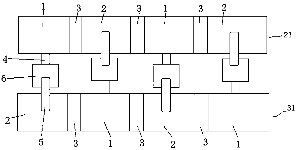
[0035] Such as figure 1 As shown, the material drying unit includes a hot air drying area 1 and a cold air drying area 2. The hot air drying area 1 dries the material through the hot air, and the cold air drying area 2 dries the material through the cold air. The hot air drying area 1 and the cold air drying area 2 are both There are more than two places, the hot air drying area 1 and the cold air drying area 2 are alternately arranged for the materials to be dried to pass through the hot air drying area 1 and the cold air drying area 2 alternately.

[0036] In this embodiment, a slow zone 3 is provided between the hot air drying area 1 and the cold air drying area 2, so as to avoid mutual influence between the hot air drying area 1 and the cold air drying area 2, and also to facilitate the transportation of materials.

[0037] Such as figure 1 As shown, the material drying unit includes two drying lines, which are respectively the first drying line 21 and the second drying l...

Embodiment 2

[0049] The difference with embodiment 1 is that the lifting conveyor belt in the specific embodiment 1 is not set in the hot air drying area and the cold air drying area, but the conveyor belt conveyed along the horizontal direction is set on the drying line, and the length of the conveyor belt is greater than Corresponding to the length of the drying line, there are three areas on the conveyor belt corresponding to the hot air drying area, slow drying area and cold air drying area. Every time the conveyor belt travels the length of a zone, it needs to stay for a period of time to dry and slow the material.

Embodiment 3

[0051] The difference from Embodiment 1 is that the cold end of a heat pump corresponds to more than two cold air drying areas, and at this time, more than two pipelines need to be drawn from the cold end to correspond to each cold air drying area; or the cold end of a heat pump The hot end corresponds to more than two hot air drying areas. At this time, the hot end needs to lead out more than two pipelines to correspond to each hot air drying area.


PUM


Abstract

The invention relates to a material drying unit, which comprises a hot air drying region and a cold air drying region. The hot air drying region is used for drying the materials by means of hot air; the cold air drying region is used for drying the materials by means of cold air; and a tempering region is arranged between the hot air drying region and the cold air drying region, and is used for buffering the temperature change from the hot air drying region to the cold air drying region or from the cold air drying region to the hot air drying region. Through setting the hot air drying region and the cold air drying region for drying materials by means of hot air and cold air correspondingly, and setting the tempering region between the hot air drying region and the cold air drying region,the materials pass through the tempering region firstly and then enter the hot air drying region after coming out of the cold air drying region, the temperature of the materials can be buffered in thetempering region to adapt to temperature changes, the materials are prevented from being overheated in the hot air drying region, and the quality of agricultural products is guaranteed.

Description

technical field [0001] The invention relates to a material drying unit. Background technique [0002] Drying units are used in many industries such as grain, feed, medicinal materials, fruit processing, wood, etc., to remove moisture from materials and achieve drying of materials. At present, drying units generally use hot air to heat materials to evaporate water out of materials. Heat sources include hot water boilers, steam boilers, heat-conducting oil furnaces, electric heating, heat pumps, etc. [0003] The Chinese patent application whose publication number is CN106839711A discloses a unit used in a tunnel-type wood veneer drying process. The unit includes a cold drying room, a hot drying room and a heat pump unit. In the long tunnel structure, the cold drying room and the hot drying room are divided into upper and lower parts. The upper space is equipped with a circulation fan, and the lower space is for materials to pass through. airflow. In addition, the evaporato...

Claims


Application Information

Patent Timeline
IPC IPC(8): F26B15/18F26B21/00F26B25/00F26B3/347
CPCF26B3/347F26B15/18F26B21/00F26B25/00
Inventor 朱广成路风银杨慧韩俊豪郭文英董俊辉董铁有
Owner 河南省农业科学院农副产品加工研究中心
Why Eureka
Try Eureka