
A Secondary Flow Evaporation Tube Combustion Chamber Structure

A technology of combustion chamber and secondary flow, which is applied in the direction of combustion chamber, continuous combustion chamber, combustion method, etc., and can solve the problems of enhancing the thermal radiation of the wall surface of the flame tube, high wall temperature, and a large amount of soot

Active Publication Date: 2021-03-16
NAT INST CORP OF ADDITIVE MFG XIAN
View PDF5 Cites 0 Cited by
  • Summary
  • Abstract
  • Description
  • Claims
  • Application Information

AI Technical Summary

Problems solved by technology

Combustion products are cooled and discharged from the combustion chamber through air mixing, and the slow mixing process will cause the combustion products to stay for too long, and form a reaction zone close to the chemically proper ratio of NOx in a certain area, which will greatly increase NOx emissions
At the same time, an excessively high oil-gas equivalence ratio will generate a large amount of soot, which will enhance the heat radiation on the wall surface of the flame tube and cause the wall temperature to be too high

Method used


Image

  • A Secondary Flow Evaporation Tube Combustion Chamber Structure
  • A Secondary Flow Evaporation Tube Combustion Chamber Structure
  • A Secondary Flow Evaporation Tube Combustion Chamber Structure

Examples


Embodiment Construction

[0030] The present invention is described in further detail below in conjunction with accompanying drawing:

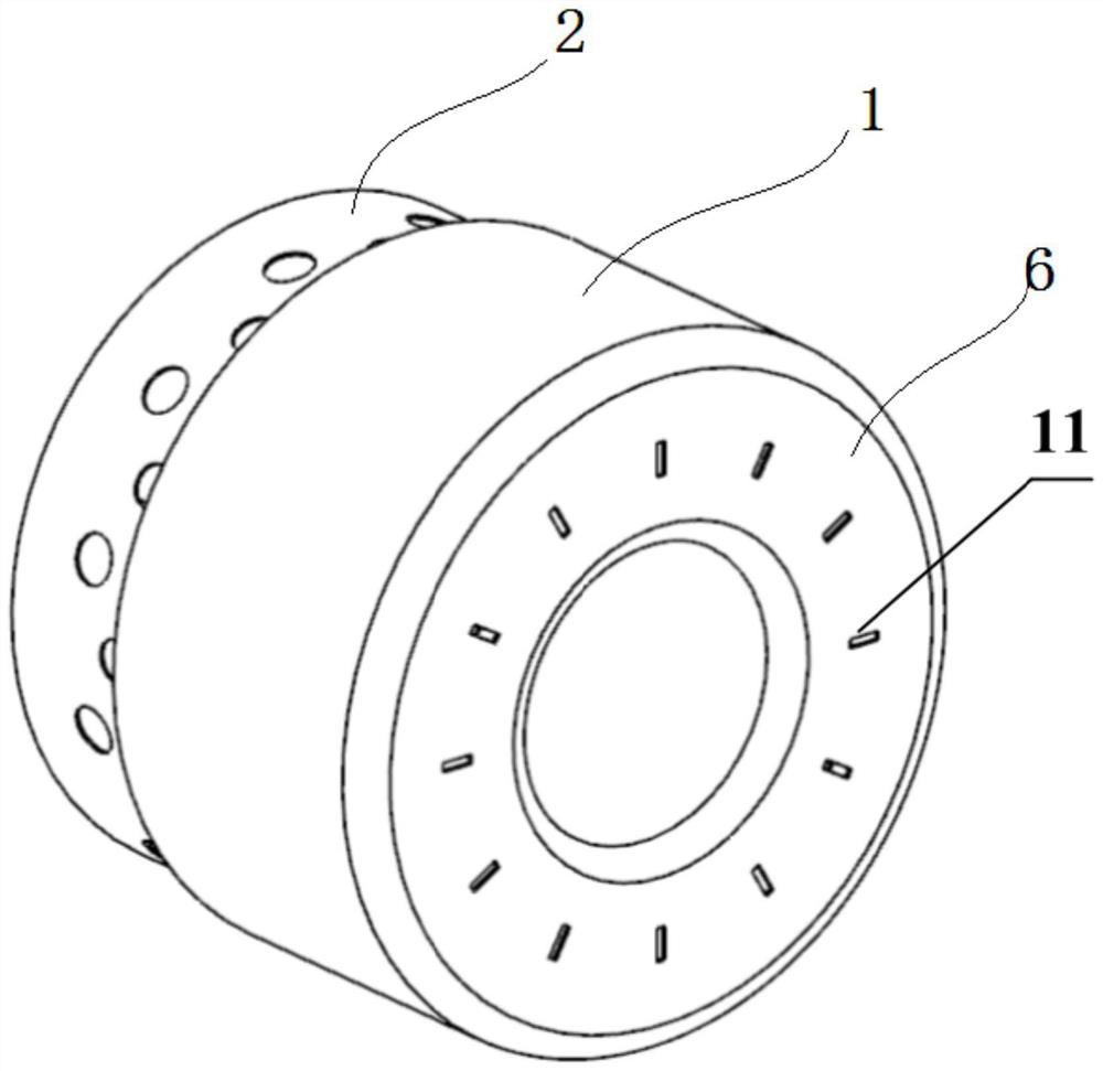
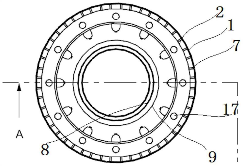
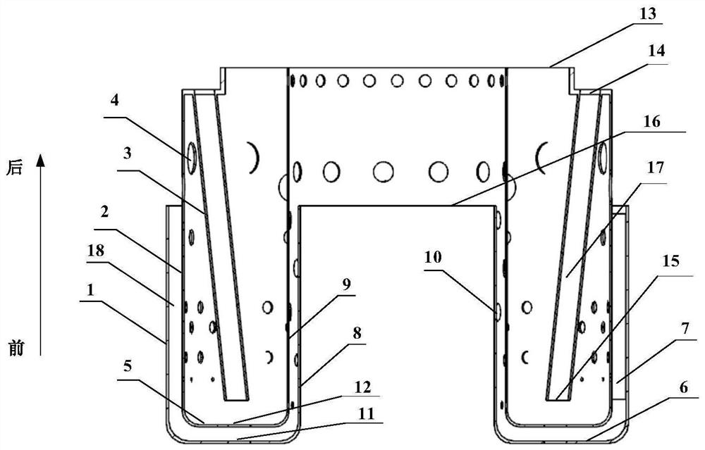
[0031] see Figure 1 to Figure 5 As shown, a secondary flow evaporating tube type combustion chamber structure includes a combustion chamber body 3 and a baffle plate 18. The combustion chamber body 3 includes an outer wall surface 2 of the combustion chamber, an inner wall surface 9 of the combustion chamber, a front wall surface 5 of the combustion chamber and a rear wall surface of the combustion chamber. The end wall surface 13 forms a flame cylinder between the combustion outer wall surface 2 and the combustion inner wall surface 9; the combustion outer wall surface 2, the combustion chamber wall surface 9 and the combustion chamber front end wall surface 5 are all provided with air film holes, and there is a circle outside the combustion chamber wall surface 2 Baffle 18, baffle 18 comprises baffle outer wall 1, baffle front end wall 6, baffle inner wall 8 and baf...


PUM


Abstract

The invention discloses a secondary-flow evaporation tube type combustion chamber structure. A combustion chamber body and a baffle plate are adopted, wherein the front end of the combustion chamber body is shaped like a cylinder, and the upper end of the baffle plate is provided with an annular groove; the baffle plate is additionally arranged on an outer wall surface of a combustion chamber, andair film holes are formed in the annular cylindrical barrel wall and the groove wall of the annular groove, so that the reverse air flow of a secondary flow in a casing is heated and heated again after being injected by a primary air flow at the head of the combustion chamber and mixed; and then the combustion flame temperature field is more uniform, the heat transfer of the fin reinforced wall surface enables the temperature of the wall surface to be effectively decreased, the uniformity of the flow field is optimized, the combustion efficiency is improved, and the emission of pollutants such as NOx is greatly reduced while fuel is saved. The annular cylindrical outer wall and the inner wall of the annular groove are connected through fins to form an integrated forming structure, the overall weight of the device is reduced, the outline size of the combustion chamber is decreased, the thrust ratio of an engine is effectively increased, and the maneuverability of the engine is increased; and the using number of connecting parts between structural members is decreased at the same time, and the overall performance is improved.

Description

technical field [0001] The invention belongs to the field of engine combustion systems, and in particular relates to a secondary flow evaporation tube type combustion chamber structure. Background technique [0002] Combustion chambers with evaporator tube structures are widely used in combustion chambers of engines and ground gas turbines, especially micro-miniature power equipment. A lot of research work has been done on micro-miniature engines abroad, and mature models of various magnitudes have been produced accordingly, forming corresponding Military and civilian markets. The combustion chamber adopting the evaporation tube scheme has the advantages of simple structure, easy processing, low cost and good comprehensive combustion performance. The weight and volume of the combustion chamber itself are an important limitation on the performance of the aircraft. It is an important design direction to reduce the weight and volume while retaining the advantages of the evapor...

Claims


Application Information

Patent Timeline
Patent Type & Authority Patents(China)
IPC IPC(8): F23R3/32
CPCF23R3/32
Inventor 张琦眭晓蔚代赟杨红伟袁元园王瑞秦岭卢秉恒
Owner NAT INST CORP OF ADDITIVE MFG XIAN
Learn More