Supporting structure for building
A supporting structure and construction technology, applied in the direction of building construction, construction, construction components on-site preparation, etc., can solve the problems of poor stability, poor corner support ability, etc., to achieve increased stability, enhanced structural strength, enhanced The effect of stability
- Summary
- Abstract
- Description
- Claims
- Application Information
AI Technical Summary
Problems solved by technology
Method used
Image

Examples
Embodiment 1
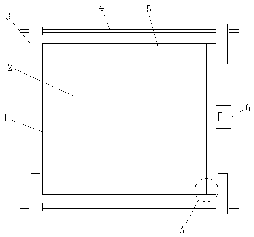
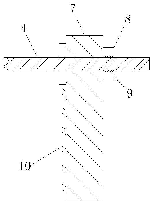
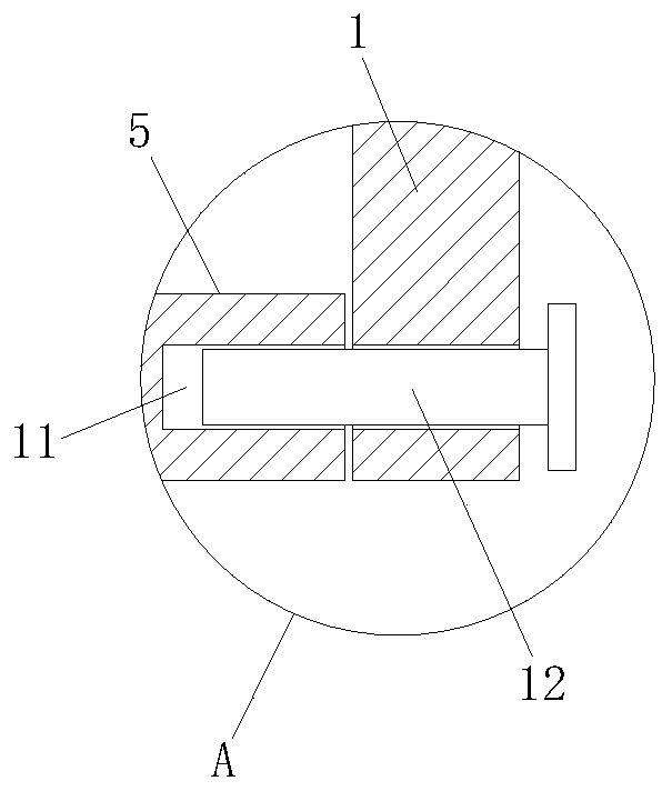
[0030] Example 1, please refer to Figure 1~3 , a supporting structure for building, comprising a first guard plate 1 and a second guard plate 5, the first guard plate 1 and the second guard plate 5 surround the outer periphery of the cylinder 2, the first guard plate 1 Fasteners 3 are respectively provided on the upper and lower sides, and threaded rods 4 are connected between the fasteners 3 on the left and right sides. Firmware 3 comprises splint 7, and splint 7 upper outer position is provided with fixed block 8, threaded rod 4 passes through fixed block 8 and splint 7, and fixed block 8 is provided with thread 9, and thread 9 is engaged with threaded rod 4, and described Empty slots 11 are provided at the left and right ends of the second guard plate 5 , and studs 12 are provided on the first guard plate 1 corresponding to the slots 11 , and the studs 12 extend into the empty slots 11 .
Embodiment 2
[0031] Example 2, please refer to Figure 1~3 , a supporting structure for building, comprising a first guard plate 1 and a second guard plate 5, the first guard plate 1 and the second guard plate 5 surround the outer periphery of the cylinder 2, the first guard plate 1 Fasteners 3 are respectively provided on the upper and lower sides, and threaded rods 4 are connected between the fasteners 3 on the left and right sides. Firmware 3 comprises splint 7, and splint 7 upper outer position is provided with fixed block 8, threaded rod 4 passes through fixed block 8 and splint 7, and fixed block 8 is provided with thread 9, and thread 9 is engaged with threaded rod 4, and described The left and right ends of the second guard plate 5 are provided with empty slots 11, and the positions corresponding to the empty slots 11 on the first guard plate 1 are provided with studs 12, and the studs 12 extend into the empty slots 11. On the splint 7, Helical teeth 10 are provided on the inner s...
Embodiment 3
[0033] Embodiment three, please refer to Figure 1~3 And 6, a support structure for building, comprising a first guard plate 1 and a second guard plate 5, the first guard plate 1 and the second guard plate 5 surround the outer periphery of the column body 2, the first guard plate Fasteners 3 are respectively provided on the upper and lower sides of the plate 1, threaded rods 4 are connected between the fasteners 3 on the left and right sides, and an auxiliary vibrator 6 is arranged on the right side of the first guard plate 1, so Described fastener 3 comprises splint 7, and splint 7 upper outer position is provided with fixed block 8, and threaded rod 4 passes through fixed block 8 and splint 7, and fixed block 8 is provided with thread 9, and thread 9 is engaged with threaded rod 4, The left and right ends of the second guard plate 5 are provided with empty slots 11, and the corresponding empty slots 11 are provided with studs 12 on the first guard plate 1, and the studs 12 e...
PUM
 Abstract
Description
Claims
Application Information
 - R&D
- Intellectual Property
- Life Sciences
- Materials
- Tech Scout
- Unparalleled Data Quality
- Higher Quality Content
- 60% Fewer Hallucinations
Browse by: Latest US Patents, China's latest patents, Technical Efficacy Thesaurus, Application Domain, Technology Topic, Popular Technical Reports.
© 2025 PatSnap. All rights reserved.Legal|Privacy policy|Modern Slavery Act Transparency Statement|Sitemap|About US| Contact US: help@patsnap.com