Desulfurization method of gas storage tank system
A gas storage tank and desulfurizer technology, applied in the field of gas purification, can solve the problems of corroded pipelines, equipment flow meters, affecting human health, and design equipment, etc., to achieve the effects of protecting the environment, stabilizing biogas quality, and ensuring product quality
- Summary
- Abstract
- Description
- Claims
- Application Information
AI Technical Summary
Problems solved by technology
Method used
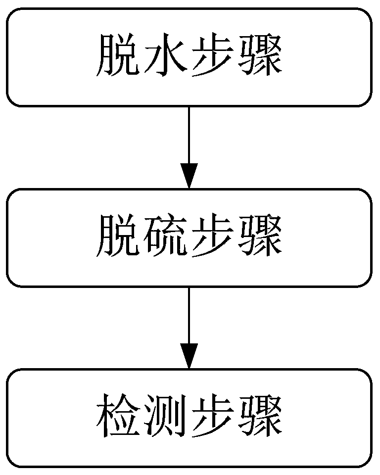
Image

Examples
Embodiment
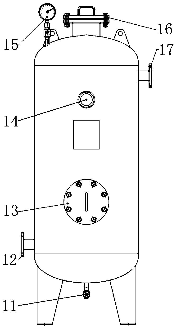
[0042] Biogas production capacity 15000m 3 / d, import hydrogen sulfide content: 1000ppm, desulfurization precision requirement: export hydrogen sulfide content is less than 10ppm.
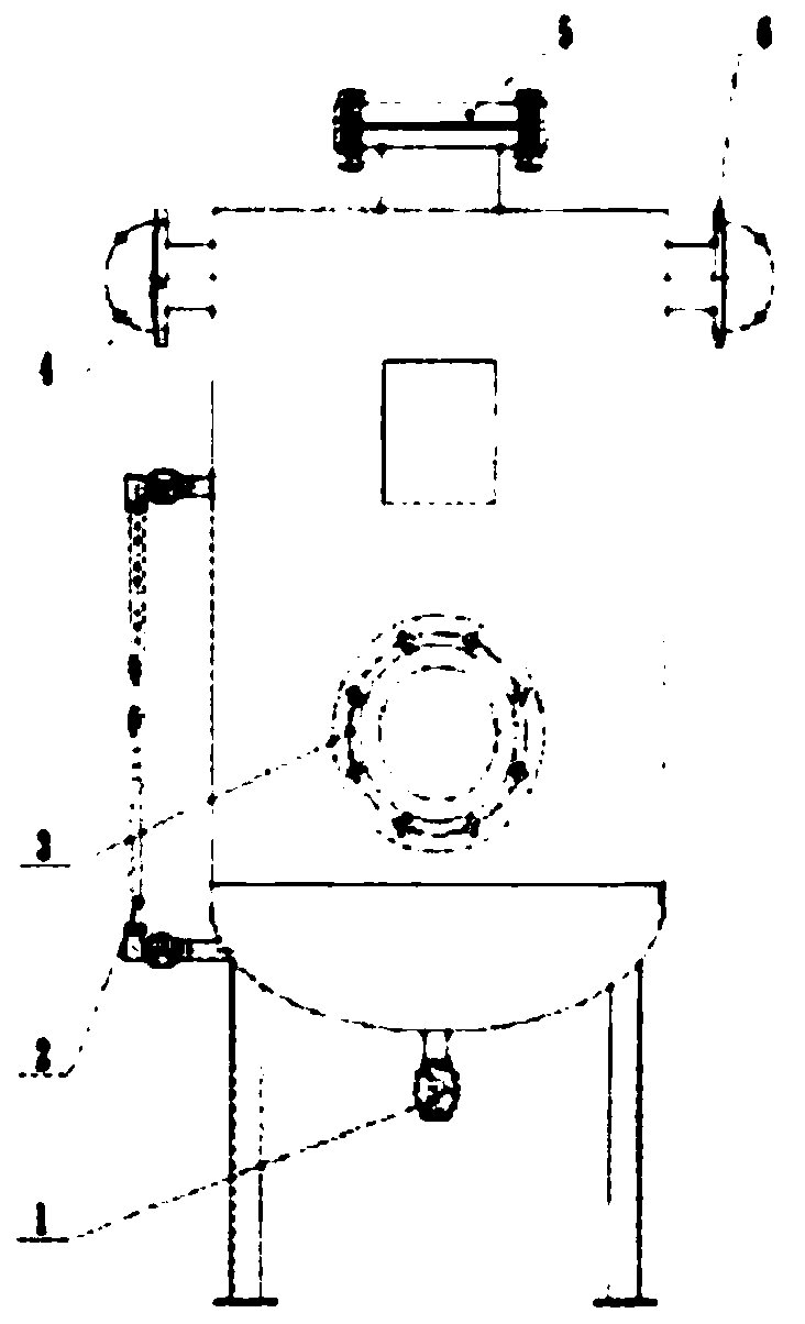
[0043] Since the biogas contains free water, it will have an adverse effect on the desulfurization of the iron oxide desulfurizer. The free water will cause the desulfurization agent to become muddy, the gas will drift, and the desulfurizer will quickly fail. Therefore, dehydration is required before desulfurization. Specifically, the dehydration device adopts a gas-water separator, and the gas-water separator adopts a gravity method to remove moisture; as figure 2 As shown, the gas-water separator is provided with a separator water outlet 1, a separator liquid level gauge 2, a separator outlet 3, a separator inlet 4, a separator inlet 5 and a separator outlet 6, The inside of the gas-water separator is provided with fillers. When the biogas enters the gas-water separator from the separator inlet...
PUM
 Abstract
Description
Claims
Application Information
 - Generate Ideas
- Intellectual Property
- Life Sciences
- Materials
- Tech Scout
- Unparalleled Data Quality
- Higher Quality Content
- 60% Fewer Hallucinations
Browse by: Latest US Patents, China's latest patents, Technical Efficacy Thesaurus, Application Domain, Technology Topic, Popular Technical Reports.
© 2025 PatSnap. All rights reserved.Legal|Privacy policy|Modern Slavery Act Transparency Statement|Sitemap|About US| Contact US: help@patsnap.com