
A positioning drilling rotary table

A technology of a rotary table and a positioning device, which is used in positioning devices, precision positioning equipment, and drilling dies for workpieces, etc., can solve the problems of drilling position accuracy deviation, time-consuming and labor-consuming, and installation difficulties, and avoid drilling holes. Variation in positional accuracy, convenient drilling process, and effect of shortening machining time

Active Publication Date: 2021-06-29
福建惠丰电机有限公司
View PDF9 Cites 0 Cited by
  • Summary
  • Abstract
  • Description
  • Claims
  • Application Information

AI Technical Summary

Problems solved by technology

When drilling, the blanks of stainless steel motor end covers are mostly made of 304 or 316 stainless steel, and their machining performance such as turning and drilling is poor. Especially in the drilling process, for multiple uniformly distributed holes, it is necessary to Single mechanical action and long-term operation are time-consuming and labor-intensive, and the processing of evenly distributed flange faces on the flange surface requires high technological requirements to ensure that customers can properly assemble the motor on the working machine
For a stainless steel motor end cover with multiple holes evenly distributed, the existing tooling equipment generally has the following deficiencies: most of them only realize the positioning and clamping of the end cover when drilling, and do not solve the problem of one-time clamping. Drilling multiple times requires repeated disassembly and assembly of the workpiece, which leads to deviations in the position accuracy of the drilling and poor process quality; the operation is complicated, the installation is difficult, and the production efficiency is not high in actual production applications.

Method used


Image

  • A positioning drilling rotary table
  • A positioning drilling rotary table
  • A positioning drilling rotary table

Examples


Embodiment 1

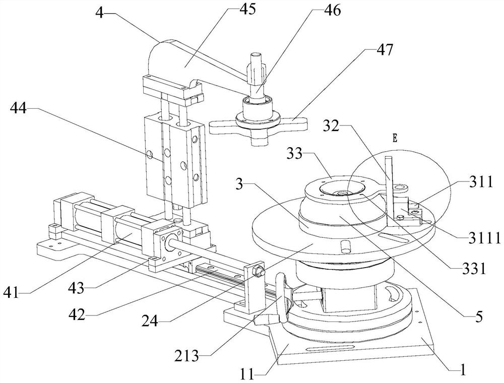
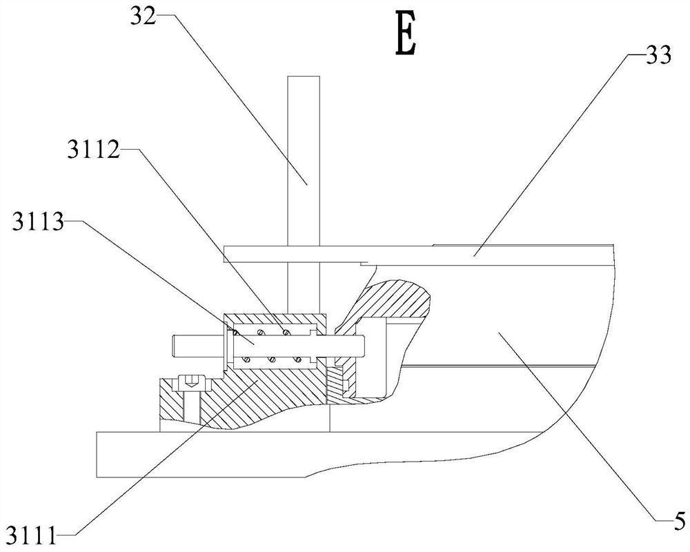
[0043]A positioning drilling rotary table, including a base 1, a turntable 2 and an end cap positioning device 3; the turntable 2 includes a driving mechanism 21, a main shaft 22, a ratchet 23 and a turntable 24; the base 1 includes a base 11 and a setting The bearing seat 12 on the top of the base 11; the main shaft 22 is vertically connected to the bearing seat 12 through bearings, the ratchet 23 is coaxially connected to the main shaft 22, and the rotating disk 24 is coaxially connected to the upper end of the main shaft 22; The driving mechanism 21 is used to drive the main shaft 22 to rotate; the bearing housing 12 includes an upper bearing housing 121 and a lower bearing housing 122, the ratchet 23 is located above the upper bearing housing 121, and the driving structure is located at the upper bearing housing 121 and the lower bearing housing between the seats 122; the base 1 is hinged with a pawl 13, and the pawl 13 cooperates with the ratchet 23; the end cover position...


PUM


Abstract

The invention relates to the field of motor drilling tooling structures, in particular to a positioning drilling rotary table; including a base, a turntable and an end cover positioning device; the turntable includes a driving mechanism, a main shaft, a ratchet and a turntable; the base includes a base and the bearing seat set on the upper part of the base; it realizes multiple drilling in one clamping, avoiding the deviation of the drilling position accuracy caused by multiple disassembly and assembly of the end cover; the original single mechanical operation is replaced by the turntable, so that the drilling The process is more convenient, which greatly shortens the processing time of drilling a flange surface of an end cover and improves production efficiency; the designed quarter-point rotary table can accurately realize the drilling of four uniformly distributed holes on the same circumference; this design The structure is distributed vertically, and each part has a simple structure, which is convenient for subsequent maintenance.

Description

technical field [0001] The invention relates to the field of motor drilling tooling structures, in particular to a positioning drilling rotary table. Background technique [0002] The end cover of the stainless steel motor is generally designed with four or six or eight holes evenly distributed on the flange end surface of the end cover, which is used for threaded connection and assembly of the motor and the working machine. When drilling, the blanks of stainless steel motor end covers are mostly made of 304 or 316 stainless steel, and their machining performance such as turning and drilling is poor. Especially in the drilling process, for multiple uniformly distributed holes, it is necessary to Single mechanical action and long-term operation are time-consuming and labor-intensive, and the processing of evenly distributed flange faces on the flange surface requires high technological requirements, so as to ensure that customers can properly assemble the motor on the working...

Claims


Application Information

Patent Timeline
Patent Type & Authority Patents(China)
IPC IPC(8): B23B47/28B23Q3/08B23Q16/06
CPCB23B47/28B23B2247/12B23Q3/062B23Q3/08B23Q16/06B23Q2703/04
Inventor 李宝民
Owner 福建惠丰电机有限公司
Learn More