High-efficiency cleaning device

A cleaning device and high-efficiency technology, applied in cleaning methods and utensils, cleaning methods using tools, cleaning methods using liquids, etc., can solve problems affecting glass recycling efficiency, facilitate subsequent processing work, and increase contact area , Improve the effect of cleaning effect

Active Publication Date: 2020-04-17
重庆华彬伟玻璃有限公司
View PDF8 Cites 1 Cited by
  • Summary
  • Abstract
  • Description
  • Claims
  • Application Information

AI Technical Summary

Problems solved by technology

[0003] The glass recovery process includes crushing, cleaning, etc., that is, glass containers such as glass bottles are broken, and then the broken glass fragments are cleaned. Since some wrapping paper or packaging plastics will adhere to some glass, in the prior art, in order to clean the glass The wrapping paper or packing plastic on the shards, in the transmission process of the glass shards, wash the glass shards with water under a certain pressure, but it is difficult to wash away the wrapping paper or packing plastic on the glass shards in this way, which will make the glass The fragments are washed multiple times, which affects the efficiency of glass recycling

Method used


Image

  • High-efficiency cleaning device
  • High-efficiency cleaning device
  • High-efficiency cleaning device

Examples


Embodiment 1

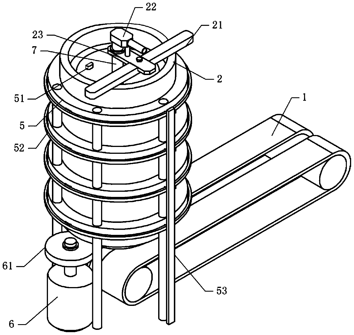
[0040] Basic as attached figure 1 , attached figure 2 And attached image 3 As shown, a high-efficiency cleaning device includes a support frame 5, a cleaning bucket 2 with openings on the upper and lower parts, the cross section of the cleaning bucket 2 is circular, and the support frame 5 is set on the outer periphery of the cleaning bucket 2. Bucket 2 is fixedly connected with support frame 5 by fastening bolt. One side of the upper opening of the cleaning bucket 2 is welded and fixed with a support rod 21, the support rod 21 is fixed with a support plate 23 by fastening bolts, the support plate 23 is rotatably connected with the transmission shaft 7 located in the cleaning bucket 2, and the transmission shaft 7 The top is rotatably connected with a hollow connection box 22, the connection box 22 is fixed on the support plate 23 by fastening bolts, the connection box 22 is connected with a water pump (not shown in the figure) through a water pipe, combined with the attac...

Embodiment 2

[0049] The difference between embodiment two and embodiment one is that, as attached Figure 5 , attached Figure 6 And attached Figure 7 As shown, the output shaft of the single-phase motor 6 is coaxially welded and fixed with a cam 65, and the gear 62 is horizontally slidably connected with a push plate 66 that is offset against the cam 65. Sliding fit grooves, an elastic member is arranged between the push plate 66 and the side wall of the cleaning bucket 2. In this embodiment, the elastic piece is a spring 67, and the two ends of the spring 67 are respectively welded on the side of the pushing plate 66 and the cleaning bucket 2. on the wall. The right side of the push plate 66 is welded with a cleaning shaft 68, and a U-shaped cleaning plate 69 is welded and fixed on the cleaning shaft 68. Expansion plates are welded and fixed on both sides of the cleaning plate 69, and one side of the conveyor belt 1 is provided with a belt fixed by fastening bolts. Fans on the rack. ...


PUM


Abstract

The invention relates to the technical field of glass cleaning, and discloses a high-efficiency cleaning device. The high-efficiency cleaning device comprises a cleaning barrel, wherein openings are formed in the upper portion and the lower portion of the cleaning barrel correspondingly, a hollow conveying shaft is rotatably connected in the cleaning barrel, a spiral blade is fixed to the periphery of the conveying shaft, the upper part of the conveying shaft communicates with a water source, the lower end of the conveying shaft is fixedly connected with a driven gear, the driven gear meshes with a driving gear driven by a driving part, a plurality of cleaning groups are arranged on the cleaning barrel in the axial direction of the cleaning barrel, each cleaning group comprises a water spray head communicating with the conveying shaft and a plurality of gas nozzles located below the water spray head, and the gas nozzles are uniformly distributed in the axial direction of the cleaning barrel. The device is simple in structure, impurities on glass fragments are cleared in the cleaning process of the glass fragments, the repeated cleaning of the glass fragments is avoided, and the cleaning efficiency of the glass fragments is improved.

Description

technical field [0001] The invention relates to the technical field of glass cleaning, in particular to a high-efficiency cleaning device. Background technique [0002] Glass is a material commonly used in modern human life. It can be made into various utensils, utensils, flat glass, etc. Therefore, after the utensils are used, more waste is generated, such as glass bottles. For the sustainable utilization of resources, discarded glass and products can be collected to turn harm into benefit and waste into wealth. [0003] The glass recovery process includes crushing, cleaning, etc., that is, glass containers such as glass bottles are broken, and then the broken glass fragments are cleaned. Since some wrapping paper or packaging plastics will adhere to some glass, in the prior art, in order to clean the glass The wrapping paper or packing plastic on the shards, in the transmission process of the glass shards, wash the glass shards with water under a certain pressure, but it ...

Claims


Application Information

Patent Timeline
Patent Type & Authority Applications(China)
IPC IPC(8): B08B3/02B08B3/10B08B5/02B08B1/02
CPCB08B3/022B08B3/104B08B5/023B08B1/20
Inventor 周昌伟张华平
Owner 重庆华彬伟玻璃有限公司
Why Eureka
Try Eureka