A motor dust and grease cleaning equipment

A technology for cleaning equipment and grease. It is used in metal processing equipment, grinding/polishing equipment, and dust removal. It can solve the problems of complicated cleaning operations and poor cleaning efficiency.

Active Publication Date: 2020-12-22
浙江申华针纺服饰有限公司
View PDF8 Cites 0 Cited by
  • Summary
  • Abstract
  • Description
  • Claims
  • Application Information

AI Technical Summary

Problems solved by technology

[0005] Aiming at the deficiencies of the prior art, the present invention provides a motor dust and grease cleaning equipment, which solves the existing technical problems of complicated cleaning operation and poor cleaning efficiency when cleaning the motor

Method used


Image

  • A motor dust and grease cleaning equipment
  • A motor dust and grease cleaning equipment
  • A motor dust and grease cleaning equipment

Examples


Embodiment 1

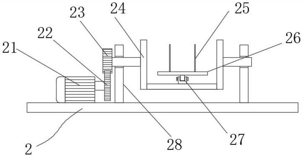
[0032] Such as Figure 1-5 As shown, a motor dust and grease cleaning equipment includes: a support plate 1, a clamping structure 2, a side vertical plate 3, a cleaning structure 4 and a pushing structure 5, and the side vertical plate 3 is vertically fixed on the top of the support plate 1 At one end of the side, the clamping structure 2 is arranged on the top side of the support plate 1, the cleaning structure 4 is arranged on the middle side of the side riser 3, and the pushing structure 5 is fixed on the top of the side riser 3;

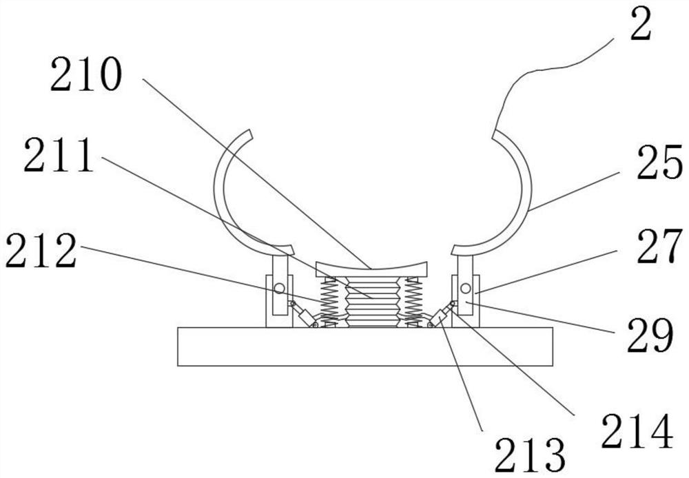
[0033]The clamping structure 2 includes a steering motor 21, a steering gear 22, a matching gear 23, a bogie 24, a clamping rod 25, a horizontal plate 26, a positioning support 27, a fixed frame 28, a swing rod 29, a bottom bracket 210, and an air bag 211, buffer spring 212, air cavity rod 213 and piston rod 214, the steering motor 21 is mounted on the top side of the support plate 1 through bolts, the steering gear 22 is fixed on the output end ...


PUM


Abstract

The invention provides motor dust and oil stain removal equipment, and relates to the technical field of motor maintenance. The equipment comprises a supporting plate, a clamping structure, a cleaningstructure and a pushing structure, wherein a side stand plate is vertically fixed at one end of the top side of the supporting plate, and the pushing structure is fixed at the top of the side stand plate. Through arrangement of the clamping structure, after clamping is carried out, a steering motor operates to drive a steering gear to rotate, and a bogie rotates in cooperation with a matching gear, and can drive a motor to be cleaned to rotate; motors of various sizes can not only be clamped, but also be rotated and turned, oil stain and dust can be sucked and collected in time in cooperationwith a pumping pipe, the surface of the motor to be cleaned can be cleaned more thoroughly in time, washing with water is not needed, and thus the loss of the motor to be cleaned is reduced; and in the cleaning process, it is ensured that the cleaning area is neat, the site does not need to be cleaned, the cleaning efficiency is improved, and the cleanness of the motor is ensured.

Description

technical field [0001] The invention relates to the technical field of motor maintenance, in particular to a device for cleaning motor dust and grease. Background technique [0002] A motor is an electromagnetic device that converts or transmits electrical energy according to the law of electromagnetic induction. In the circuit, it is represented by the letter M (the old standard is D). Its main function is to generate driving torque as a power source for electrical appliances or various machines. The generator is represented by the letter G in the circuit. Its main function is Use mechanical energy to convert into electrical energy, the most commonly used at present is to use heat energy, water energy, etc. to drive the rotor of the generator to generate electricity; [0003] After the existing motor is used for a long time, dust and grease will accumulate on the surface of the motor, which will affect the heat dissipation capacity of the motor. When cleaning the motor, it...

Claims


Application Information

Patent Timeline
Patent Type & Authority Patents(China)
IPC IPC(8): B08B1/02B08B13/00B24B27/033B08B15/04
CPCB08B1/002B08B1/02B08B13/00B08B15/04B24B27/033
Inventor 芦伟
Owner 浙江申华针纺服饰有限公司
Why Eureka
Try Eureka