Micro-current apparent power sensing method and device

A sensing method and sensing device technology, applied in the direction of apparent power measurement, electrical device, and measuring electric power, etc., can solve problems such as inability to detect current development process, hidden dangers in production and life, and sudden power outages, so as to avoid Sudden tripping and power failure, stable and reliable performance, and the effect of reducing losses

Pending Publication Date: 2020-04-14
山东计保电气有限公司
View PDF0 Cites 0 Cited by
  • Summary
  • Abstract
  • Description
  • Claims
  • Application Information

AI Technical Summary

Problems solved by technology

[0004] The above protective measures all belong to the category of post-protection. Only when the destructive energy of the current develops to a certain extent and reaches the protection threshold, it will act. It is a method to start the protection through power failure. Early preventive treatment without compromising safety can hinder its development and even eliminate budding failures
And once the protection threshold is reached, a sudden power failure will occur, which will bring serious hidden dangers to production and life, especially equipment involving people, such as elevators, transportation and entertainment equipment, etc.
[0005] In reality, the grounding current, insulation current or leakage current is usually very small and intermittent, large and small, and extremely unstable, so that the measured value cannot truly reflect the destructive power in the power system, making it impossible to solve the long-term impact on the power grid. Safe operation and seriously affecting the quality of power supply. Therefore, it is necessary to develop a new detection technology that can reflect the change of energy destruction, so as to take security measures in time, and then avoid disorderly power outages, achieve safe and energy-saving production, and reduce waste. Purpose

Method used


Image

  • Micro-current apparent power sensing method and device
  • Micro-current apparent power sensing method and device

Examples


Embodiment Construction

[0033] The present invention will be further described in detail below in conjunction with the accompanying drawings and specific embodiments.

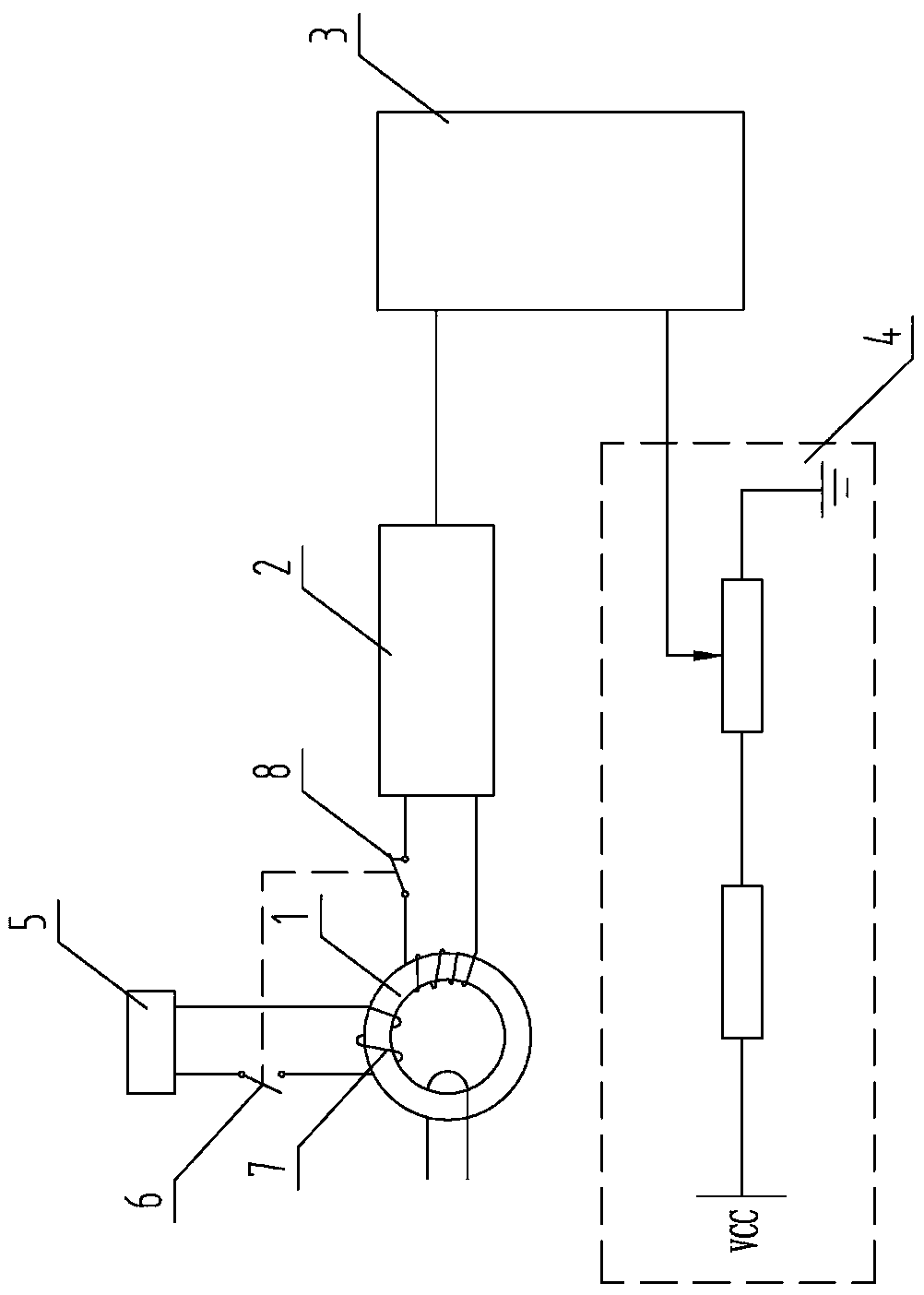
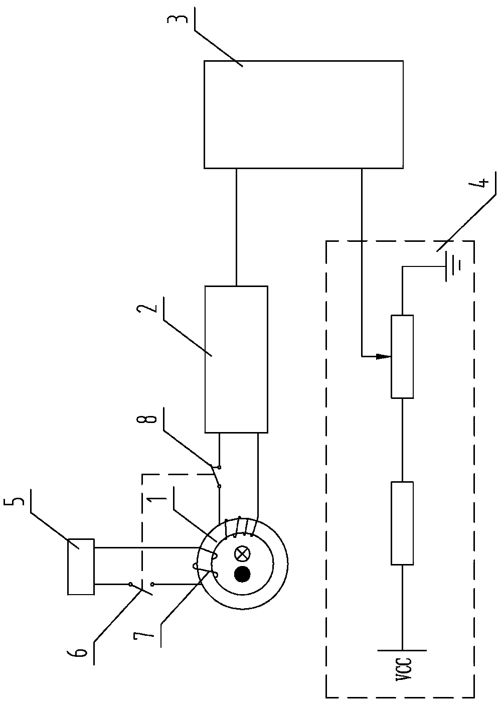
[0034] The gist of the present invention is: use the current detection device to detect the current on the ground wire of the equipment, the zero-sequence current line or the ground lead of the insulation part, and multiply the detected current by a given apparent voltage to form an apparent power , the apparent power is accumulated to obtain the apparent power, and then the apparent power is read every interval of the same length of time to see the amount of change in the apparent power in the same period, if the change in the apparent power in each time period The range of change is not large, and it is basically in a stable state, which means that the destructive power on the line has not changed significantly. Continue to maintain the above time interval to read the apparent power and check the change of the apparent power; if the ...


PUM


Abstract

The invention discloses a micro-current apparent power sensing method and a device, and belongs to the technical field of electromagnetic measurement, and the method comprises the steps: S1, detectinga grounding wire, a grounding lead of an insulating part or a micro-current on a zero-sequence current line, and obtaining a current on a corresponding line; S2, carrying out current acquisition on the micro current detected in the step S1, and multiplying the micro current by a pre-judged given apparent voltage to obtain apparent power; and S3, accumulating the apparent power obtained in the S2in real time to obtain the apparent electric quantity. According to the method, the grounding small current, the insulation current or the leakage current can be converted into an apparent electric quantity form accumulated along with time, so that the change trend of the electric power destructive power can be considered in a time period, necessary security check measures can be taken conveniently, disordered power failure is avoided, and an electric power foundation is laid for guaranteeing normal production.

Description

technical field [0001] The invention belongs to the technical field of electromagnetic measurement, and in particular relates to a microcurrent apparent power sensing method and device. Background technique [0002] Since the end of the 1960s, in order to strengthen the safety of electricity use, my country has gradually adopted protection measures in the power system, among which the leakage protector is a general technical means. The leakage protector detects the abnormal current or voltage signal of the monitoring equipment or the circuit. When the detected signal reaches its set threshold, it prompts the actuator to act to cut off the power supply, so as to avoid accidents such as burning out electrical appliances, fire or electric shock, so as to ensure personal safety and health. To ensure the safety of electrical equipment and achieve the purpose of protection. [0003] Later, some also adopted the method of small current grounding, which installed a zero-sequence cu...

Claims


Application Information

Patent Timeline
IPC IPC(8): G01R21/00G01R21/06G01R22/06G01R19/00G01R31/52G01R31/12G01R31/08
CPCG01R19/0092G01R21/005G01R21/06G01R22/06G01R31/085G01R31/1272
Inventor 荣博荣潇杨剑郭亮张海静丁淑洁宋增祥宋淄琳刘宇鹏
Owner 山东计保电气有限公司
Why Eureka
Try Eureka