
3D hydraulic forming method for special-shaped sealing ring of aero-engine

An aero-engine and hydroforming technology, which is applied in the field of sealing ring manufacturing, can solve problems such as inability to ensure accurate synchronous loading, poor dimensional accuracy of formed parts, and poor wall thickness uniformity, so as to shorten the search trial and error interval, poor dimensional accuracy, Precise effect of material flow control

Active Publication Date: 2020-04-14
BEIHANG UNIV +1
View PDF8 Cites 6 Cited by
  • Summary
  • Abstract
  • Description
  • Claims
  • Application Information

AI Technical Summary

Problems solved by technology

[0003] Existing hydraulic forming currently uses the method of pressing down the upper mold and closing the mold to ensure the mold feed, which can only ensure the loading in two directions, and cannot guarantee the accurate simultaneous loading of the front mold, rear mold, and hydraulic pressure in three directions, resulting in the formation of parts. Poor dimensional accuracy, poor wall thickness uniformity, serious mold wear, even abnormal deformation, low yield rate, and few methods for forming special-shaped sealing rings through accurate and synchronous loading in three directions, so there is an urgent need for special-shaped sealing rings. forming method research

Method used


Image

  • 3D hydraulic forming method for special-shaped sealing ring of aero-engine
  • 3D hydraulic forming method for special-shaped sealing ring of aero-engine
  • 3D hydraulic forming method for special-shaped sealing ring of aero-engine

Examples


Embodiment 1

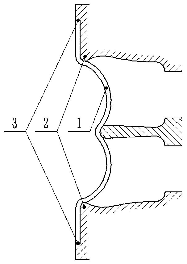
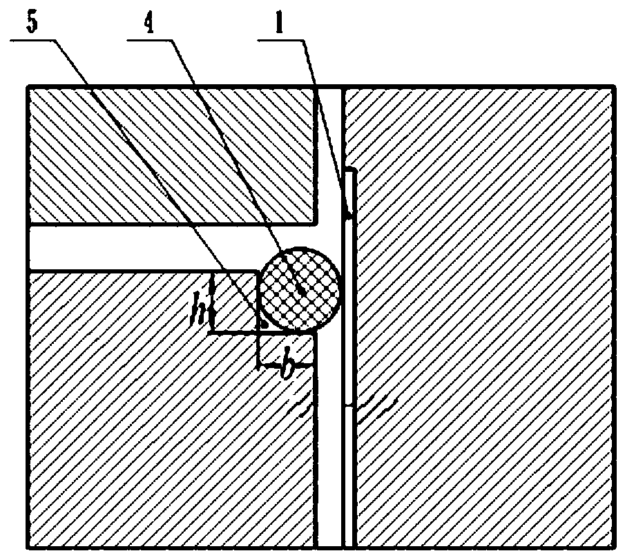
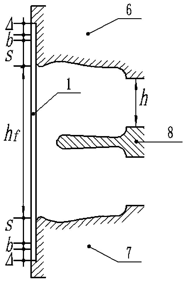
[0049] S1: Determine the blank feeding method, such as figure 1shown. The two ends of the blank 1 are stuck in the limit step groove 3 of the front mold 6 and the rear mold 7, the blank 1 and the limit step groove 3 are kept in close contact and relatively static, and the blank is pre-expanded and close to the front mold 6 And the lip area 2 of the rear mold 7, under the action of hydraulic pressure and axial feed, rely on the blank 1, the limit step groove 3 and the lip area 2 to generate static friction, transmit the axial load, push the blank to bulge and deform, and finally form It is an M-shaped sealing ring. During the forming process, the blank 1 does not participate in the deformation in the area of ​​the limiting step groove 3, which restricts the flow of materials and controls the amount of deformed materials.

[0050] S2: Design the sealing structure of the forming device, such as figure 2 shown. The sealing structure of the forming device affects the precise c...


PUM

PropertyMeasurementUnit
diameteraaaaaaaaaa

Abstract

The invention discloses a 3D hydraulic forming method for a special-shaped sealing ring of an aero-engine. The 3D hydraulic forming method comprises the steps of designing a blank feeding mode, designing a sealing structure of a forming device, designing the blank size, designing a loading path and the mold opening height, and conducting 3D hydraulic forming on the special-shaped sealing ring. Bymeans of the 3D hydraulic forming method, a better forming effect is brought to an 'M' or 'W' or double-corrugated special-shaped sealing ring of the aero-engine, and the precision and the yield of the sealing ring can be remarkably improved.

Description

technical field [0001] The invention belongs to the technical field of sealing ring manufacturing, and in particular relates to a 3D hydraulic forming method for special-shaped sealing rings of aero-engines. Background technique [0002] The sealing ring is a key part of the gas path sealing under the conditions of high temperature and high pressure, vibration and strong corrosion in aerospace. It is widely used in aero-engines. The deformation path is complex. Hydroforming is one of the mainstream technologies for forming special-shaped sealing rings. It uses liquid medium and molds to deform the blank to form parts, which has the characteristics of low cost and high limit. [0003] Existing hydraulic forming currently uses the method of pressing down the upper mold and closing the mold to ensure the mold feed, which can only ensure the loading in two directions, and cannot guarantee the accurate simultaneous loading of the front mold, rear mold, and hydraulic pressure in ...

Claims


Application Information

Patent Timeline
Patent Type & Authority Applications(China)
IPC IPC(8): B21D26/021B21D26/031B21D26/027
CPCB21D26/021B21D26/027B21D26/031
Inventor 孟宝万敏宋炳毅
Owner BEIHANG UNIV
Learn More