MCB circuit breaker wiring terminal protection device

A terminal block and protection device technology, which is applied in the direction of emergency protection device, protection switch terminal/connection, circuit, etc., can solve the problems that the cover is easy to drop and open, the hole wall gap increases, and is inconvenient, so as to improve the sealing performance. Long life, reduced friction loss, and large opening angle

Pending Publication Date: 2020-04-10
DELIXI ELECTRIC
View PDF0 Cites 2 Cited by
  • Summary
  • Abstract
  • Description
  • Claims
  • Application Information

AI Technical Summary

Problems solved by technology

[0003] One is that the splicing line at the screw will be affected by the torsion during wiring, which will cause tension on the hole wall and cause the gap to increase, especially when using an impact-type electric or pneumatic screwdriver, when the shell exceeds the bearing capacity, it will produce irreparable plastic deformation ,Affect the appearance;
[0004] Second, because the wiring screw holes are open, the protection level is only IP20. In order to improve the IP protection level, a cover is usually added to the terminal, but the cover is separated from the shell, and the cover is easy to fall and it is inconvenient to open;
[0005] The third is that when the cover and the base are assembled and riveted, there will be an assembly line in the middle of the shell. The assembly line may appear obvious due to processing accuracy, mold, shrinkage of plastic parts, etc., which will affect the appearance and affect the customer's first perception.

Method used


Image

  • MCB circuit breaker wiring terminal protection device
  • MCB circuit breaker wiring terminal protection device
  • MCB circuit breaker wiring terminal protection device

Examples


Embodiment Construction

[0036] The present invention will be described in detail below in conjunction with the accompanying drawings and specific embodiments. This embodiment is carried out on the premise of the technical solution of the present invention, and detailed implementation and specific operation process are given, but the protection scope of the present invention is not limited to the following embodiments.

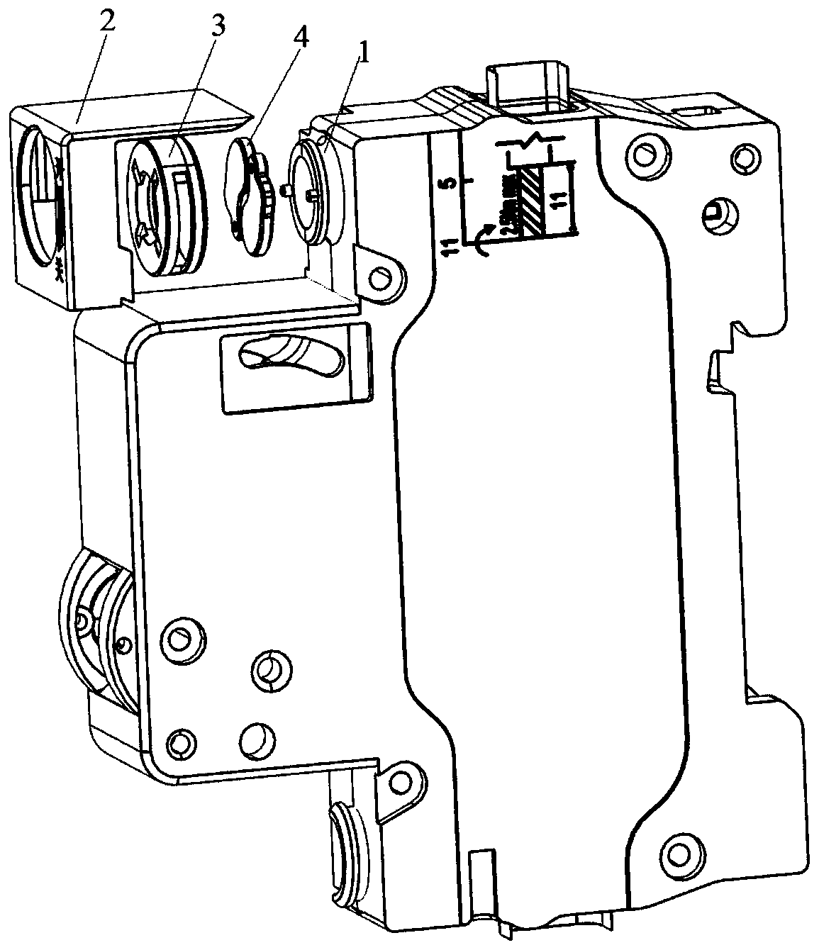
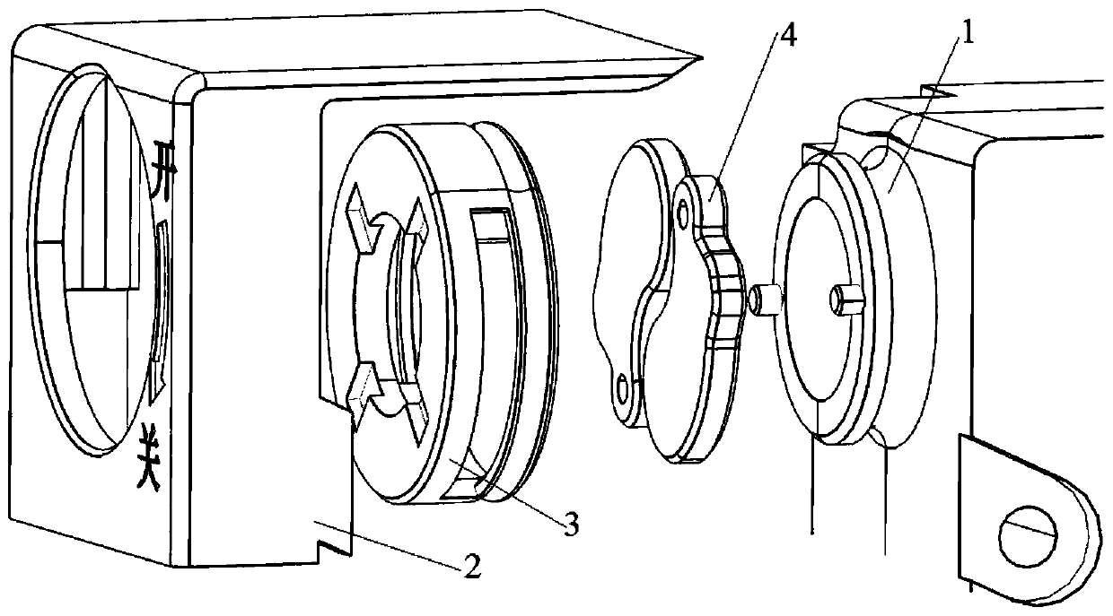
[0037] A MCB circuit breaker terminal protection device, such as figure 1 with figure 2 , used to protect the terminal blocks of MCB circuit breakers, including base 1, cover 2, rotating base 3 and 2 pieces of protective cover 4.

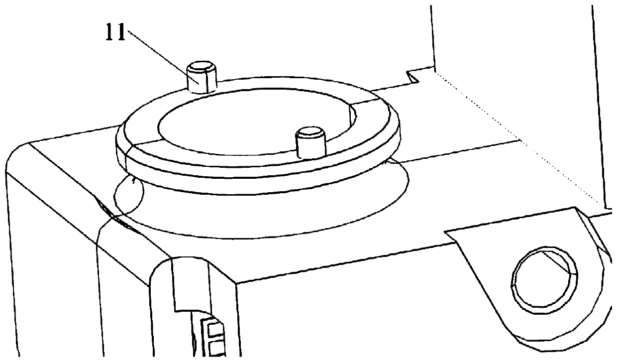
[0038] Such as image 3 , The base 1 is a circular tube structure with an inwardly recessed outer wall and is coaxially arranged at the round hole of the terminal of the MCB circuit breaker. Two fulcrum pins 11 are symmetrically arranged on the annular surface of the end face of the base 1 .

[0039] Such as Figure 5 with Image 6The rotating base 3 ...


PUM


Abstract

The invention relates to an MCB circuit breaker wiring terminal protection device. The device comprises a base (1), a cover cap (2), a rotary base (3) and two protective covers (4), the base (1) is ofa circular tube structure, and two fulcrum bolts (12) are symmetrically arranged on the end face of the base (1). The rotating base (3) is of a round cover structure, and two transmission plug pins (31) are symmetrically arranged on the inner surface of the end face of the rotating base (3). The rotary base (3) is arranged in the cover cap (2), and circular through holes are formed in the front end surface and the rear end surface of the cover cap (2) and the end surface of the rotary base (3); the round through hole in the rear end face of the cover cap (2) is hooped on the base (1), a fixing hole (41) and a limiting groove (42) are correspondingly formed in the upper surface and the lower surface of each protective cover (4), and the fulcrum plug pin (11) and the transmission plug pin (31) are inserted into the limiting grooves (42) and the fixing holes (41) of the protective covers (4) respectively. Compared with the prior art, the device has the advantages of simple operation, high protection level and the like.

Description

technical field [0001] The invention relates to the technical field of circuit breakers, in particular to an MCB circuit breaker terminal protection device. Background technique [0002] MCB (Micro Circuit Breaker / Miniature Circuit Breaker) circuit breaker is a miniature circuit breaker, which is the most widely used terminal protection device in building electrical terminal power distribution devices. It has advanced structure, reliable performance, strong breaking capacity and beautiful appearance. Small and exquisite, it is used for overload and short circuit protection of lighting, distribution lines and equipment of office buildings, residential buildings, etc., and can be used for on-off and conversion lines. The current general-purpose MCB circuit breaker shell is composed of a bottom and a cover. Due to factors such as product structure, assembly process, and mold structure, it is designed into two parts, and the assembly line is in the middle. figure 2 , the wiring...

Claims


Application Information

Patent Timeline
Patent Type & Authority Applications(China)
IPC IPC(8): H01H71/02H01H71/08
CPCH01H71/02H01H71/08
Inventor 俞华彬祁卫华
Owner DELIXI ELECTRIC
Why Eureka
Try Eureka