Wear range limiting gate valve

A stroke limit and gate valve technology, applied in the field of wear stroke limit gate valve, can solve the problem of inability to intuitively judge the wear allowance of the gate plate

Inactive Publication Date: 2020-04-10
河南富嘉流体控制技术有限公司
View PDF4 Cites 0 Cited by
  • Summary
  • Abstract
  • Description
  • Claims
  • Application Information

AI Technical Summary

Problems solved by technology

[0005] The invention provides a wear stroke limit gate valve, which solves the problem that the existing gate valve cannot intuitively judge the wear margin of the gate plate

Method used


Image

  • Wear range limiting gate valve
  • Wear range limiting gate valve
  • Wear range limiting gate valve

Examples


Embodiment Construction

[0024] The technical solutions of the present invention will be clearly and completely described below in conjunction with specific embodiments of the present invention. Apparently, the described embodiments are only some of the embodiments of the present invention, not all of them. Based on the embodiments of the present invention, all other embodiments obtained by persons of ordinary skill in the art without making creative efforts belong to the protection scope of the present invention.

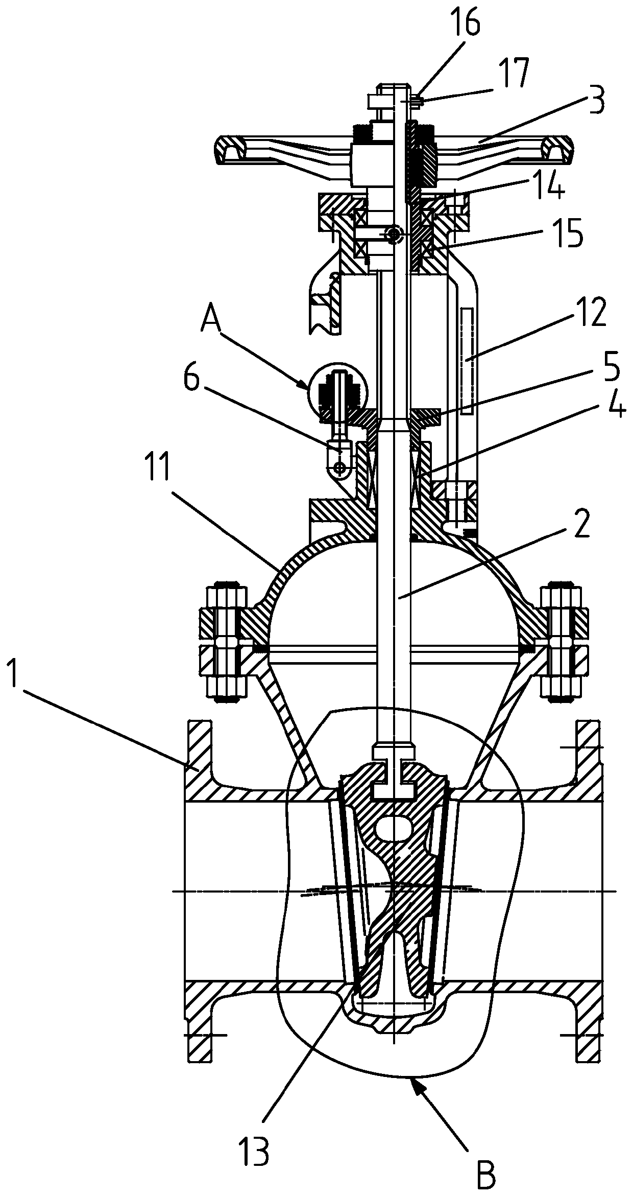
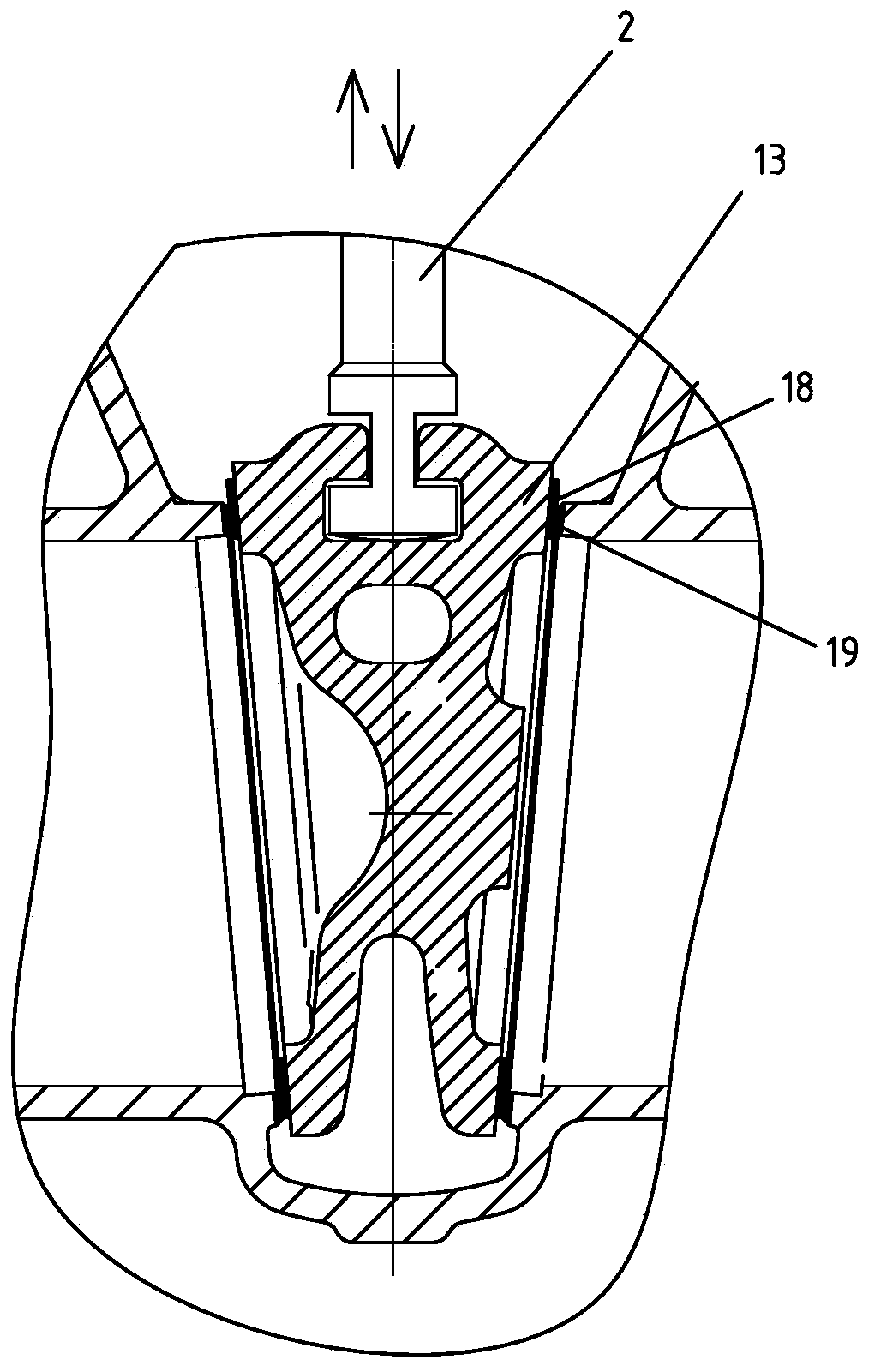
[0025] Such as Figure 1-Figure 3 As shown, this embodiment provides a wear stroke limit gate valve, including a valve body 1, a valve cover 11, a valve stem 2, a gate plate 13 and a bracket 12, the valve body 1 is fixedly connected to the valve cover 11, and the lower end of the valve stem 2 The gate plate 13 is fixedly connected, and the gate sealing surface 18 and the valve body sealing surface 19 are all surfacing with a hard alloy layer. The hard alloy layer can be 1Cr13, STL6, stainl...


PUM


Abstract

The invention discloses a wear range limiting gate valve and belongs to the technical field of valves. The wear range limiting gate valve comprises a valve body, a valve deck, a valve rod, a gate plate and a support. The valve body is fixedly connected with the valve deck. The lower end of the valve rod is fixedly connected with the gate plate. The part, extending out of the valve deck, of the valve rod is sleeved with a valve rod nut. The valve rod nut is in threaded connection with the valve rod. The valve rod nut is fixedly connected with the support through a bearing. The upper portion ofthe valve rod nut is sleeved with a hand wheel. The wear range limiting gate valve is characterized in that cemented carbide layers are welded to the sealing surface of the gate plate and the sealingsurface of the valve body in a surfacing welding mode. The part, extending out of the hand wheel, of the valve rod is sleeved with a range limiting device. Through the wear range limiting gate valve,the wear allowance of a gate plate seal can be visually found, and the service life of the gate plate can be visually controlled; and there is the intuitive basis for grinding the gate plate or replacing the gate plate.

Description

technical field [0001] The invention relates to the technical field of valves, in particular to a wear stroke limiting gate valve. Background technique [0002] The opening and closing part of the gate valve is the gate, and the movement direction of the gate is perpendicular to the direction of the fluid. The gate valve can only be fully opened and fully closed, and cannot be adjusted or throttled. The gate valve of the gate valve moves in a straight line with the valve stem, which is also called a rising stem gate valve. Usually there is a trapezoidal thread on the lifter, and through the nut at the top of the valve and the guide groove on the valve body, the rotating motion is changed into a straight line motion, that is to say, the operating torque is changed into the operation thrust. When the valve is opened, when the lift height of the gate plate is equal to 1:1 times the diameter of the valve, the passage of the fluid is completely unblocked, but this position canno...

Claims


Application Information

Patent Timeline
Patent Type & Authority Applications(China)
IPC IPC(8): F16K3/02F16K3/12F16K37/00F16K41/02F16K25/00
CPCF16K3/0263F16K3/12F16K25/005F16K37/0008F16K41/02
Inventor 王环宇
Owner 河南富嘉流体控制技术有限公司
Why Eureka
Try Eureka