
Standby bearing device of magnetic suspension bearing system

A technology of magnetic suspension bearings and bearing devices, which is applied in the direction of magnetic bearings, bearings, shafts and bearings, etc., can solve the problems of spare bearing peak impact, spare bearing damage, etc., and achieve the effects of reducing occupied space, saving cost, and not easy to age

Pending Publication Date: 2020-04-10
沈阳微控新能源技术有限公司
View PDF0 Cites 0 Cited by
  • Summary
  • Abstract
  • Description
  • Claims
  • Application Information

AI Technical Summary

Problems solved by technology

At the same time, since the magnetic bearing has no physical contact with the shafting in the working state, there is a larger gap between the spare bearing and the shafting, and when the shafting falls onto the spare bearing, it will cause a transient spike impact on the spare bearing
In addition, since the backup bearing needs to keep the shafting stable until it stops, it may experience multiple and different flexible and rigid natural frequency modes of the system during the deceleration process of the shafting. When passing through these speeds, the resonance energy will affect the backup Great damage to bearings

Method used


Image

  • Standby bearing device of magnetic suspension bearing system
  • Standby bearing device of magnetic suspension bearing system
  • Standby bearing device of magnetic suspension bearing system

Examples


Embodiment Construction

[0023] In order to make the object, technical solution and advantages of the present invention clearer, the present invention will be further described in detail below in conjunction with the accompanying drawings and specific embodiments. It should be understood that the specific embodiments described here are only used to explain the present invention, not to limit the present invention.

[0024] In the following text, many aspects of the invention will be better understood with reference to the accompanying drawings. Components in the figures are not necessarily drawn to scale. Instead, emphasis is placed on clearly illustrating the components of the invention. Furthermore, like reference numerals indicate corresponding parts throughout the several views of the drawings.

[0025] As used herein, the word "exemplary" or "illustrative" means serving as an example, instance, or illustration. Any implementation described herein as "exemplary" or "illustrative" is not necessa...


PUM


Abstract

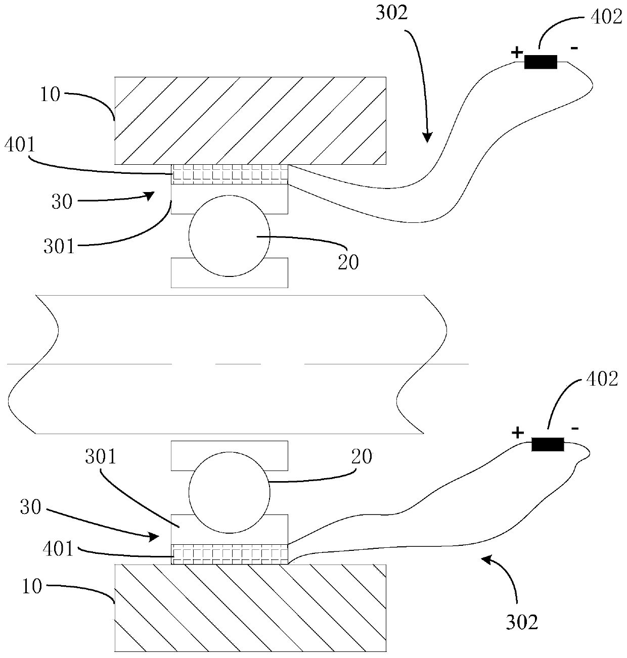
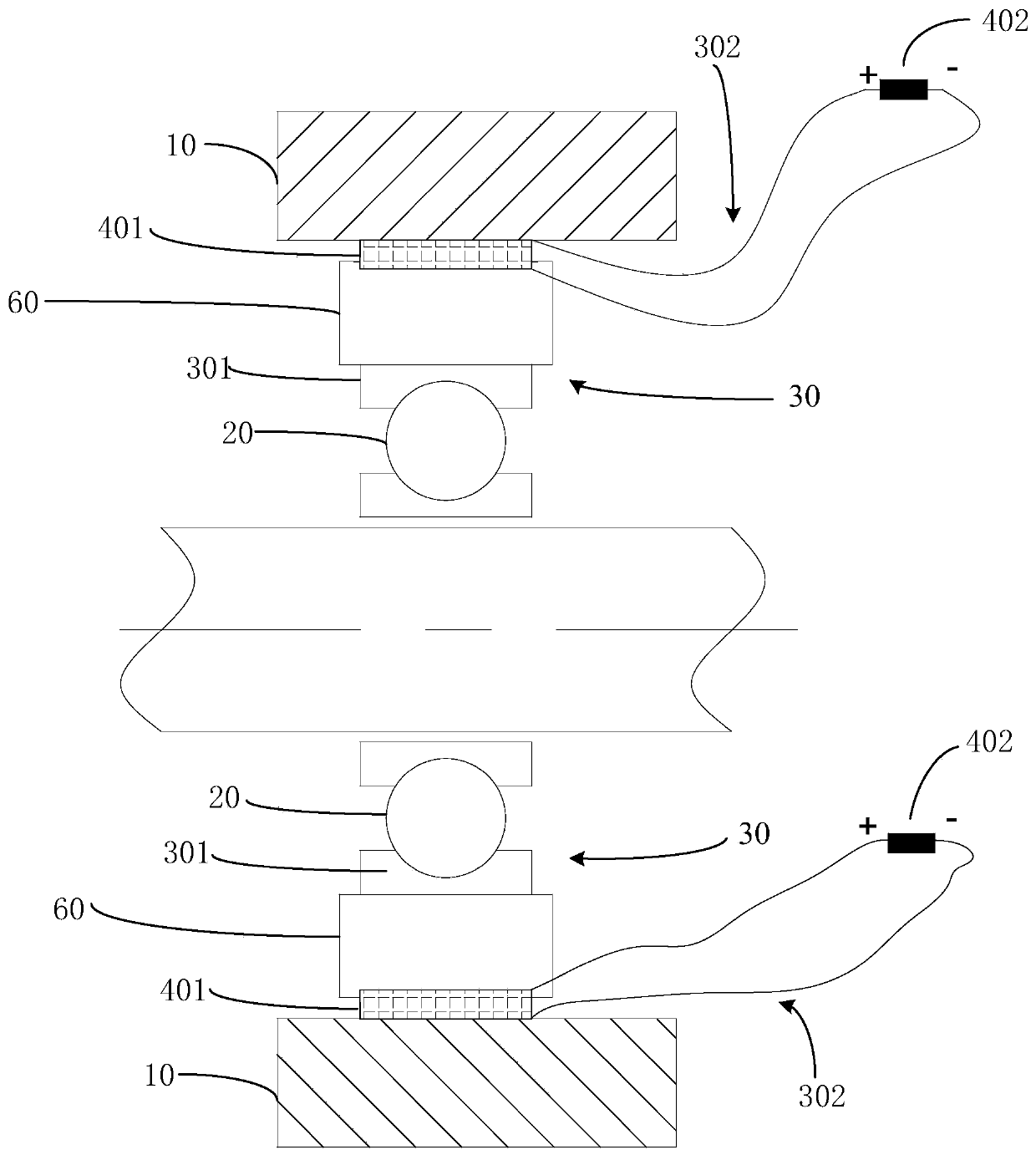
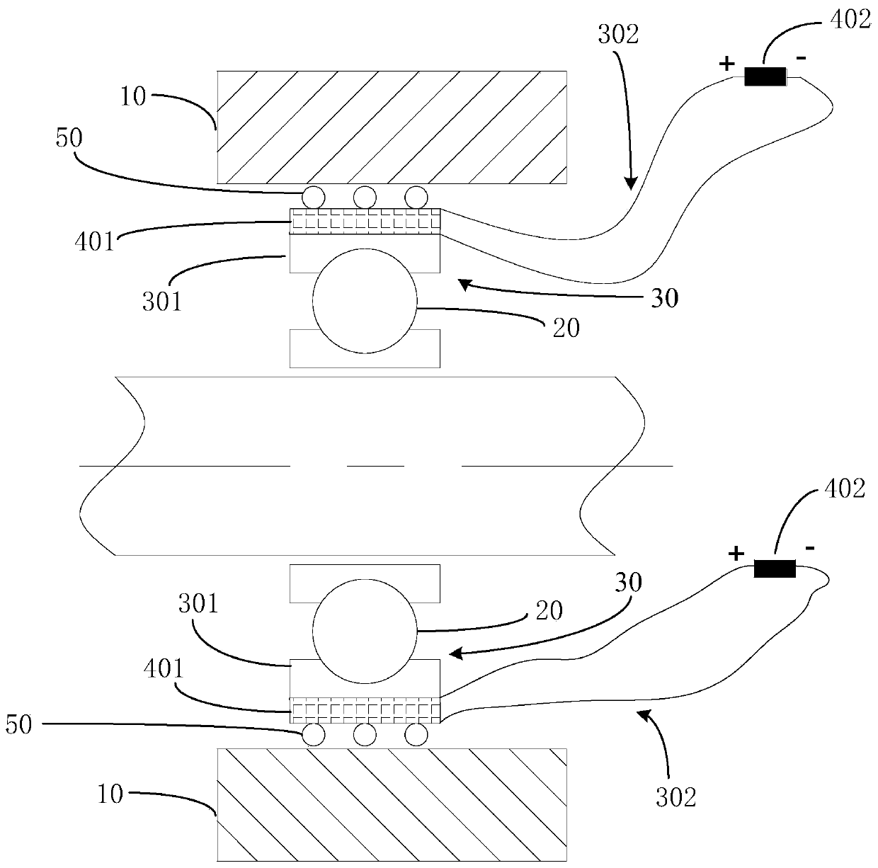
The invention relates to the technical field of bearing protection, in particular a standby bearing device of a magnetic suspension bearing system. The magnetic suspension bearing system comprises: ahousing, a rotor in the housing, magnetic bearings and standby bearing devices. The standby bearing devices are matched with the magnetic bearings, and are backups for the magnetic bearings, and the standby bearing devices are used for bearing the rotor and arranged on the two sides of the rotor. The standby bearing device comprises a standby bearing and a damping assembly, wherein the inner sideof the damping assembly is connected with the standby bearing, the outer surface of the damping assembly is matched with the housing, the damping assembly comprises a piezoelectric damper, the piezoelectric damper comprises a damping element and a resistor element connected with the damping element in series, and the damping element is made of piezoelectric materials. According to the standby bearing device, vibration and impact energy of the standby bearing is converted into electric energy through the piezoelectric damper, the electric energy is consumed by the resistor element, and therefore, the purpose of guaranteeing reliable operation of the standby bearing is achieved.

Description

technical field [0001] The invention relates to the technical field of bearing protection, in particular to a backup bearing device of a magnetic suspension bearing system. Background technique [0002] The magnetic suspension bearing system must be equipped with corresponding spare bearings, so that when the magnetic suspension bearing fails, such as power failure, overload and control system instability, it can continue to support the shafting and maintain stability, and at the same time quickly decelerate the machine to achieve The role of ensuring safe shutdown. [0003] The spare bearing usually does not work, and is only used when the magnetic suspension bearing fails, so the required life is limited. Therefore, its designed bearing capacity and rotational speed are much higher than ordinary contact bearings that can withstand continuous operation. limit. In addition, since the shafting speed of the magnetic suspension bearing system is much higher than the limit tha...

Claims


Application Information

Patent Timeline
Patent Type & Authority Applications(China)
IPC IPC(8): F16C32/04F16F15/00F16F15/12
CPCF16C32/0402F16C32/0468F16C32/047F16C2202/36F16F15/007F16F15/1207
Inventor 王智洋张庆源
Owner 沈阳微控新能源技术有限公司
Learn More