Lifting stand column with small installation distance

A technology of lifting column and installation distance, which is applied in the direction of lifting device, etc., can solve the problems of large installation distance of lifting column, inconvenient transportation, high height, etc., and achieve the effect of reducing installation distance, compact axial and radial directions, and stable transmission

Pending Publication Date: 2020-04-10
ZHEJIANG JIECHANG LINEAR MOTION TECH
View PDF0 Cites 2 Cited by
  • Summary
  • Abstract
  • Description
  • Claims
  • Application Information

AI Technical Summary

Problems solved by technology

[0002] The lifting column has been widely used in daily life due to the advantages of adjustable height and convenient transportation. The installation distance of the lifting column refers to the height of the lifting column when it is in a contracted state. Currently, the lifting column on the market is generally a two-section lifting column. Pipe or three-section lifting tube, in order to meet the longer stroke, the installation distance of the lifting column is relatively large, so that the height of the lifting column is still high when it is in the contracted state, and the handling is still not convenient

Method used


Image

  • Lifting stand column with small installation distance
  • Lifting stand column with small installation distance
  • Lifting stand column with small installation distance

Examples


Embodiment 1

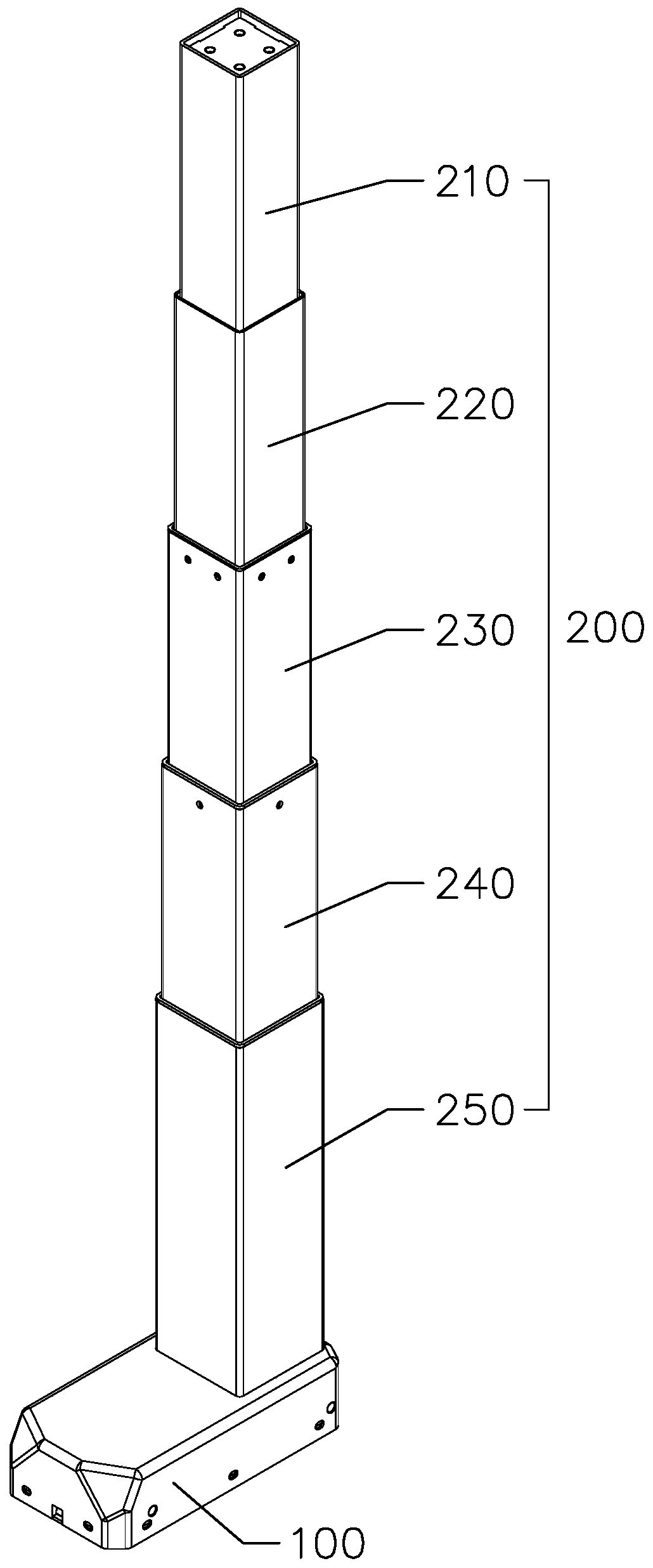
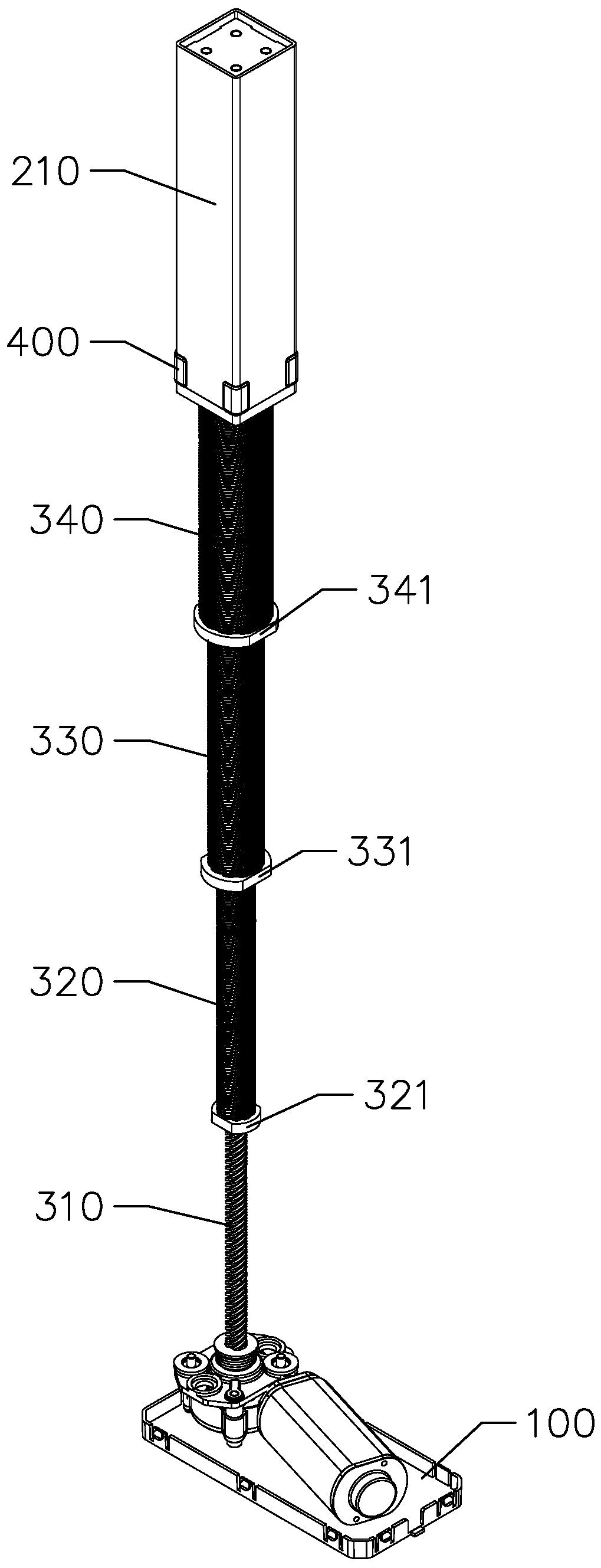
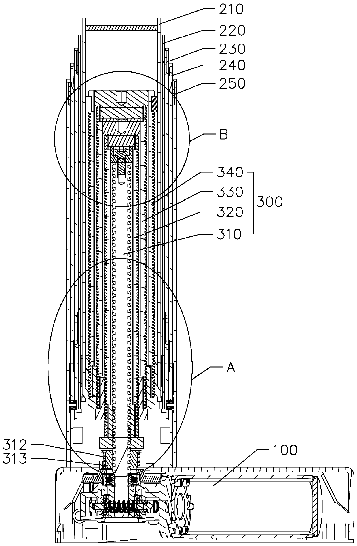
[0037] Such as Figure 1 to Figure 4 As shown, the present invention provides a lifting column with a low installation distance, including a driving device 100, a lifting tube 200 and a transmission assembly 300 inside the lifting tube 200. The lifting tube 200 includes a first tube 210, The second pipe 220, the third pipe 230, the fourth pipe 240 and the fifth pipe 250, by setting the lifting column into five sections, the installation distance of each section of the lifting pipe can be reduced, so that the installation distance is relatively low, and the fifth pipe 250 The lower end of the first pipe 210 is fixed on the driving device 100, the driving device is located at the lower end of the lifting column, the upper end of the first tube 210 is fixed on the lifting platform, the lifting column is in an upside-down state, and the transmission assembly 300 includes the first wires that are sequentially fitted from the inside to the outside. The rod 310, the second hollow scr...

Embodiment 2

[0048] The main difference between the present embodiment and the first embodiment is that the lifting column is in the normal installation state.

[0049] Such as Figure 7 and Figure 8 As shown, the lifting column is in the normal installation state, the driving device 100 is fixed on the lifting platform, the lifting tube 200 is located at the lower end of the driving device 100, the first nut 321 is located at the upper end of the second screw rod 320, and the second nut 331 is located at the third screw rod 320. On the upper end of the rod 330 , the third nut 341 is located on the upper end of the fourth screw rod 340 , and the fourth nut 221 is located on the upper end of the first tube 210 .


PUM


Abstract

The invention provides a lifting stand column with a small installation distance. The lifting stand column comprises a driving device, a lifting pipe and a transmission assembly. The lifting pipe comprises a first pipe, a second pipe, a third pipe, a fourth pipe and a fifth pipe. The lower end of the fifth pipe is fixed to the driving device. The transmission assembly comprises a first screw rod,a second screw rod, a third screw rod and a fourth screw rod. The output end of the driving device is in transmission fit with the first screw rod and can drive the first screw rod to rotate. The lower end of the second screw rod is provided with a first nut in threaded transmission connection with the first screw rod. The lower end of the third screw rod is provided with a second nut in threadedtransmission connection with the second screw rod. The lower end of the fourth screw rod is provided with a third nut in threaded transmission connection with the third screw rod. The lower end of thefirst pipe is provided with a fourth nut in threaded transmission connection with the fourth screw rod. The adjacent screw rods are in threaded transmission connection, in addition, each nut is located between the corresponding two adjacent screw rods, the transmission assembly can be more compact in the axial direction and the radial direction, and the small installation distance and the large stroke of the lifting stand column are achieved.

Description

technical field [0001] The invention relates to the technical field of lifting columns, in particular to a lifting column with a low installation distance. Background technique [0002] The lifting column has been widely used in daily life due to the advantages of adjustable height and convenient transportation. The installation distance of the lifting column refers to the height of the lifting column when it is in a contracted state. Currently, the lifting column on the market is generally a two-section lifting column. Pipe or three-section lift tube, in order to meet the longer stroke, the installation distance of the lifting column is relatively large, so that the height of the lifting column is still high when the lifting column is in a contracted state, and the transportation is still not convenient enough. Contents of the invention [0003] The object of the present invention is to provide a lifting column with a low installation distance. [0004] In order to achie...

Claims


Application Information

Patent Timeline
Patent Type & Authority Applications(China)
IPC IPC(8): B66F3/10
CPCB66F3/10B66F3/18
Inventor 胡仁昌陆小健潘坚
Owner ZHEJIANG JIECHANG LINEAR MOTION TECH
Why Eureka
Try Eureka