A transmission assembly for a lifting column and a lifting column

A lifting column and assembly technology, applied in the direction of lifting frame, lifting device, etc., can solve the problems that affect the user's experience and easily generate vibration, and achieve the effect of improving shock absorption, reducing force, and stable transmission

Active Publication Date: 2020-09-18
ZHEJIANG JIECHANG LINEAR MOTION TECH
View PDF7 Cites 0 Cited by
  • Summary
  • Abstract
  • Description
  • Claims
  • Application Information

AI Technical Summary

Problems solved by technology

[0002] At present, the lifting columns of lifting mechanisms such as lifting tables and lifting chairs on the market often set the driving device on the upper end of the transmission assembly and directly fix the driving device on the bottom surface of the lifting plane to realize the connection between the lifting column and the lifting plane. The motor is prone to vibration during use, and the vibration of the motor is easily transmitted to the lifting plane, which makes the lifting plane vibrate greatly during the lifting process, which affects the user's experience

Method used


Image

  • A transmission assembly for a lifting column and a lifting column
  • A transmission assembly for a lifting column and a lifting column
  • A transmission assembly for a lifting column and a lifting column

Examples


Embodiment 1

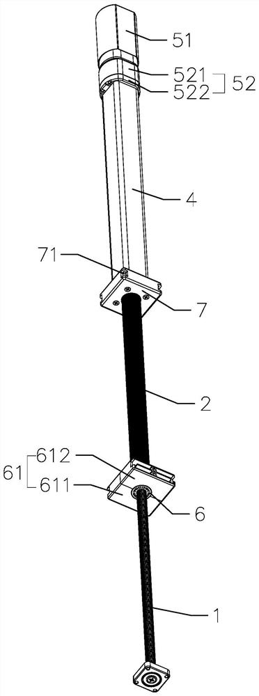
[0040] Such as Figure 1 to Figure 6 As shown, the present invention provides a transmission assembly for a lifting column. The lifting column includes an inner tube 8, and the transmission assembly includes a hollow shaft 2 provided with an external thread, a transmission screw 1 located in the hollow shaft 2, a sleeve A sleeve 4 outside the hollow shaft 2, a guide tube 3 rotatably limited in the sleeve 4, and a drive device 5 for driving the guide tube 3 to rotate, the guide tube 3 and the hollow shaft 2 can be synchronized Rotate and the guide tube 3 and the hollow shaft 2 can be relatively stretched along the axial direction, the transmission screw 1 can rotate synchronously with the hollow shaft 2 and the transmission screw 1 and the hollow shaft 2 can be relatively stretched along the axial direction, the driving device 5 is located at The inner tube 8 is fixedly installed on the upper end of the casing 4, the lower end of the casing 4 is fixedly connected with the first...

Embodiment 2

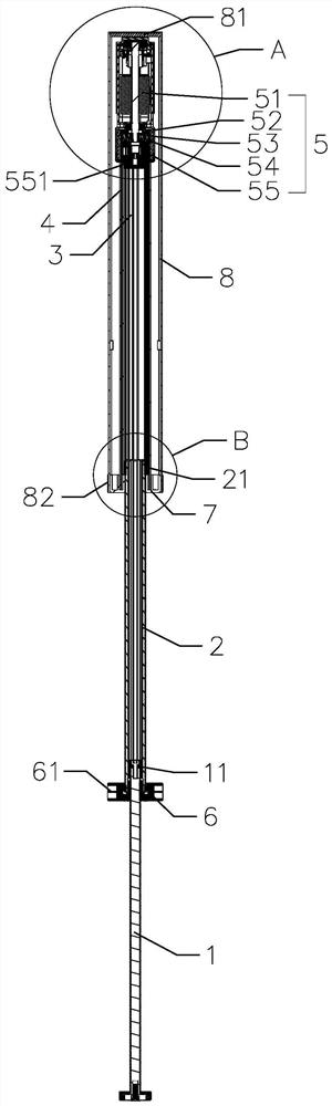
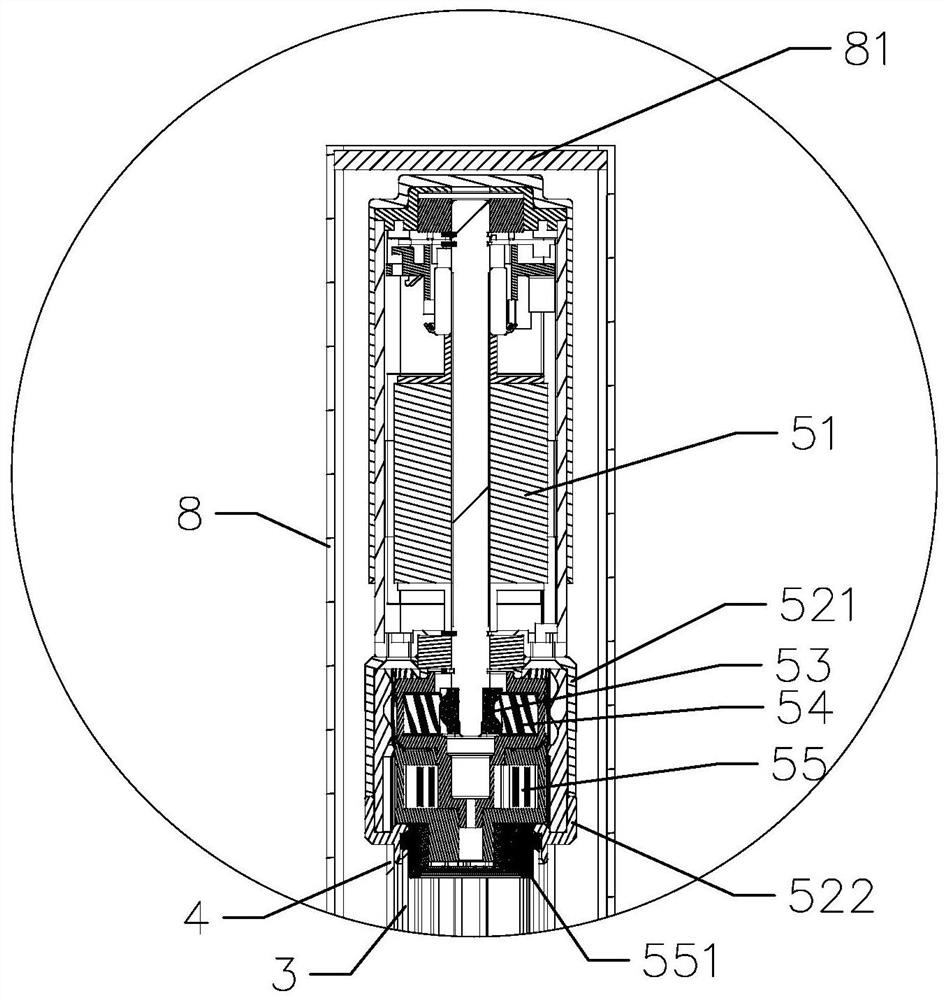
[0058] Such as Figure 8 As shown, the main difference between this embodiment and Embodiment 1 is that the top plate 81 is a flexible top plate, that is, the top plate is made of flexible materials. At this time, the driving device can be arranged without a gap between the flexible top plate, and the flexible top plate can buffer the driving device. vibration.

Embodiment 3

[0060] Such as Figure 9 As shown, the main difference between this embodiment and the first embodiment is that the transmission assembly further includes a middle pipe 10 , and the middle pipe 10 is located between the inner pipe 8 and the outer pipe 9 . The advantage of this setting is that the installation distance of the lifting column can be reduced by setting the three-section pipe for synchronous expansion and contraction.

[0061] In this embodiment, the lower end of the hollow shaft 2 is provided with a second drive nut 6 with a fixed circumferential position, and the second drive nut 6 is screwed with the drive screw 1, and the hollow shaft 2 is rotatably connected to the second drive nut. 6 is positioned in the axial direction, and the outside of the second drive nut 6 is provided with a lock structure 61 that limits the rotation of the second drive nut 6. The lock structure 61 is fixedly connected to the lower end of the middle tube 10, and the second drive nut 6 i...


PUM


Abstract

The invention provides a transmission assembly for a lifting column and a lifting column. The lifting column includes an inner tube. The guide tube and the driving device for driving the guide tube to rotate, the guide tube and the hollow shaft can rotate synchronously and the guide tube and the hollow shaft can be relatively stretched along the axial direction, the transmission screw can rotate synchronously with the hollow shaft and the transmission screw and The hollow shaft can be relatively stretched along the axial direction. The driving device is located in the inner tube and is fixedly installed on the upper end of the sleeve. The lower end of the sleeve is fixedly connected with the first transmission nut threaded with the hollow shaft. The pipe is fixedly connected, and the upper end of the casing is freely set. The vibration caused by the driving device is transmitted to the first transmission nut through the casing, and will not be directly transmitted to the lifting platform above the inner pipe, so that the vibration feeling is reduced, and the transmission of the transmission assembly It is more stable, and the vibration of lifting column lifting is small.

Description

technical field [0001] The invention relates to the technical field of lifting columns, in particular to a transmission assembly for a lifting column and a lifting column. Background technique [0002] At present, the lifting columns of lifting mechanisms such as lifting tables and lifting chairs on the market often set the driving device on the upper end of the transmission assembly and directly fix the driving device on the bottom surface of the lifting plane to realize the connection between the lifting column and the lifting plane. The motor is prone to vibration during use, and the vibration of the motor is easily transmitted to the lifting plane, which makes the lifting plane vibrate greatly during the lifting process, which affects the user's experience. Contents of the invention [0003] The object of the present invention is to provide a transmission assembly for a lifting column and a lifting column with stable transmission. [0004] In order to achieve the abov...

Claims


Application Information

Patent Timeline
Patent Type & Authority Patents(China)
IPC IPC(8): B66F7/12B66F7/28
CPCB66F7/12B66F7/28B66F3/10B66F3/20B66F3/16
Inventor 不公告发明人
Owner ZHEJIANG JIECHANG LINEAR MOTION TECH
Why Eureka
Try Eureka