Flexible solar cell front panel and manufacturing method thereof, and flexible solar cell
A solar cell and manufacturing method technology, which is applied in the directions of circuits, photovoltaic power generation, electrical components, etc., can solve the problems of increasing the cost of flexible solar cell front panels, many process steps, etc., and achieves simplified manufacturing method steps, good light transmittance, and thickness. thin effect
- Summary
- Abstract
- Description
- Claims
- Application Information
AI Technical Summary
Problems solved by technology
Method used
Image
Examples
Embodiment 1
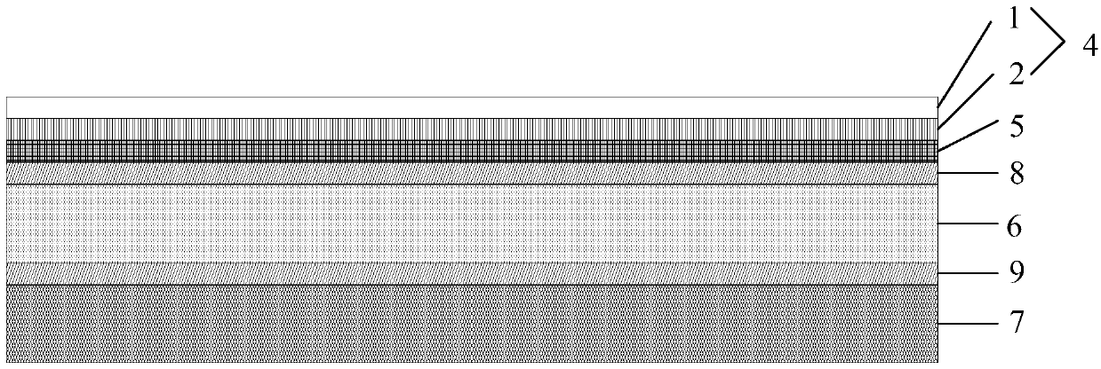
[0022] Such as figure 1 As shown, this embodiment provides a flexible solar cell front sheet, comprising: a weather-resistant layer 1 , a base layer 2 , and a water-blocking layer 5 arranged in sequence.
[0023] The weather-resistant layer 1, the base layer 2, and the water-blocking layer 5 are transparent. The weather-resistant layer 1, the base layer 2, and the water-blocking layer 5 are transparent. The functions of the weather-resistant layer 1 are reinforcement, weather resistance, UV resistance, moisture resistance, low dielectric constant, and high breakdown voltage. The function of the base layer 2 is to block water and isolate oxygen. The function of the water blocking layer 5 is high water blocking.
[0024] It should be noted that, in this embodiment, the weather-resistant layer 1 is a polymer weather-resistant layer, and the material of the weather-resistant layer 1 includes a fluoropolymer, and the fluoropolymer is ethylene-tetrafluoroethylene copolymer (ETFE)...
Embodiment 2
[0034] This embodiment provides a flexible solar cell front plate, which differs from the flexible solar cell front plate in Embodiment 2 as follows:
[0035] The thickness of the weather-resistant layer is 18 μm, the thickness of the base layer is 180 μm, and the thickness ratio of the weather-resistant layer to the base layer is 1:10.
[0036]This embodiment provides a method for manufacturing the above-mentioned flexible solar cell front plate, which is different from the method in Embodiment 2 in that: the temperature zones of the first extruder for extrusion are: 282°C, 305°C, and 325°C , 340°C; the head temperature of the first extruder is 350°C, and the eye film temperature of the multi-layer co-extrusion die head corresponding to the first extruder is 345°C. The extruding temperature zones of the second extruder are: 250°C, 275°C, 275°C, 282°C, 272°C. The draw ratio at the time of extrusion by the second extruder was 3.5. Specifically, the extruder in this embodiment...
Embodiment 3
[0039] This embodiment provides a flexible solar cell front plate, which differs from the flexible solar cell front plate in Embodiment 2 as follows:
[0040] The thickness of the weather-resistant layer is 60 μm, the thickness of the base layer is 120 μm, and the thickness ratio of the weather-resistant layer to the base layer is 1:2.
[0041] This embodiment provides a method for manufacturing the above-mentioned flexible solar cell front plate, which differs from the method in Embodiment 2 in that: the first extruder performs extrusion and the temperature zones are: 290°C, 310°C, and 330°C , 345°C; the head temperature of the first extruder is 360°C, and the eye film temperature of the multi-layer co-extrusion die head corresponding to the first extruder is 350°C. The extruding temperature zones of the second extruder are: 260°C, 285°C, 280°C, 285°C, 275°C. The draw ratio was 4 when extruding with the second extruder. Specifically, the extruder in this embodiment is a scr...
PUM
| Property | Measurement | Unit |
|---|---|---|
| Thickness | aaaaa | aaaaa |
| Thickness | aaaaa | aaaaa |
| Thickness | aaaaa | aaaaa |
Abstract
Description
Claims
Application Information
 - R&D
- Intellectual Property
- Life Sciences
- Materials
- Tech Scout
- Unparalleled Data Quality
- Higher Quality Content
- 60% Fewer Hallucinations
Browse by: Latest US Patents, China's latest patents, Technical Efficacy Thesaurus, Application Domain, Technology Topic, Popular Technical Reports.
© 2025 PatSnap. All rights reserved.Legal|Privacy policy|Modern Slavery Act Transparency Statement|Sitemap|About US| Contact US: help@patsnap.com


