
Valve, in particular expansion valve

A technology for expansion valves and valve components, applied in the field of valves that control fluid flow, can solve the problems of expensive shells and cumbersome manufacturing, and achieve the effect of optimizing other characteristics and reducing visual appearance

Inactive Publication Date: 2020-04-07
ROBERT BOSCH GMBH
View PDF5 Cites 0 Cited by
  • Summary
  • Abstract
  • Description
  • Claims
  • Application Information

AI Technical Summary

Problems solved by technology

However, such valve element housings made of aluminum are expensive, since they are complex to produce and in some cases have to be post-processed

Method used


Image

  • Valve, in particular expansion valve
  • Valve, in particular expansion valve

Examples


Embodiment Construction

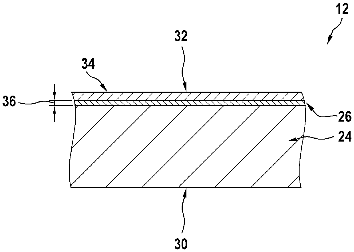
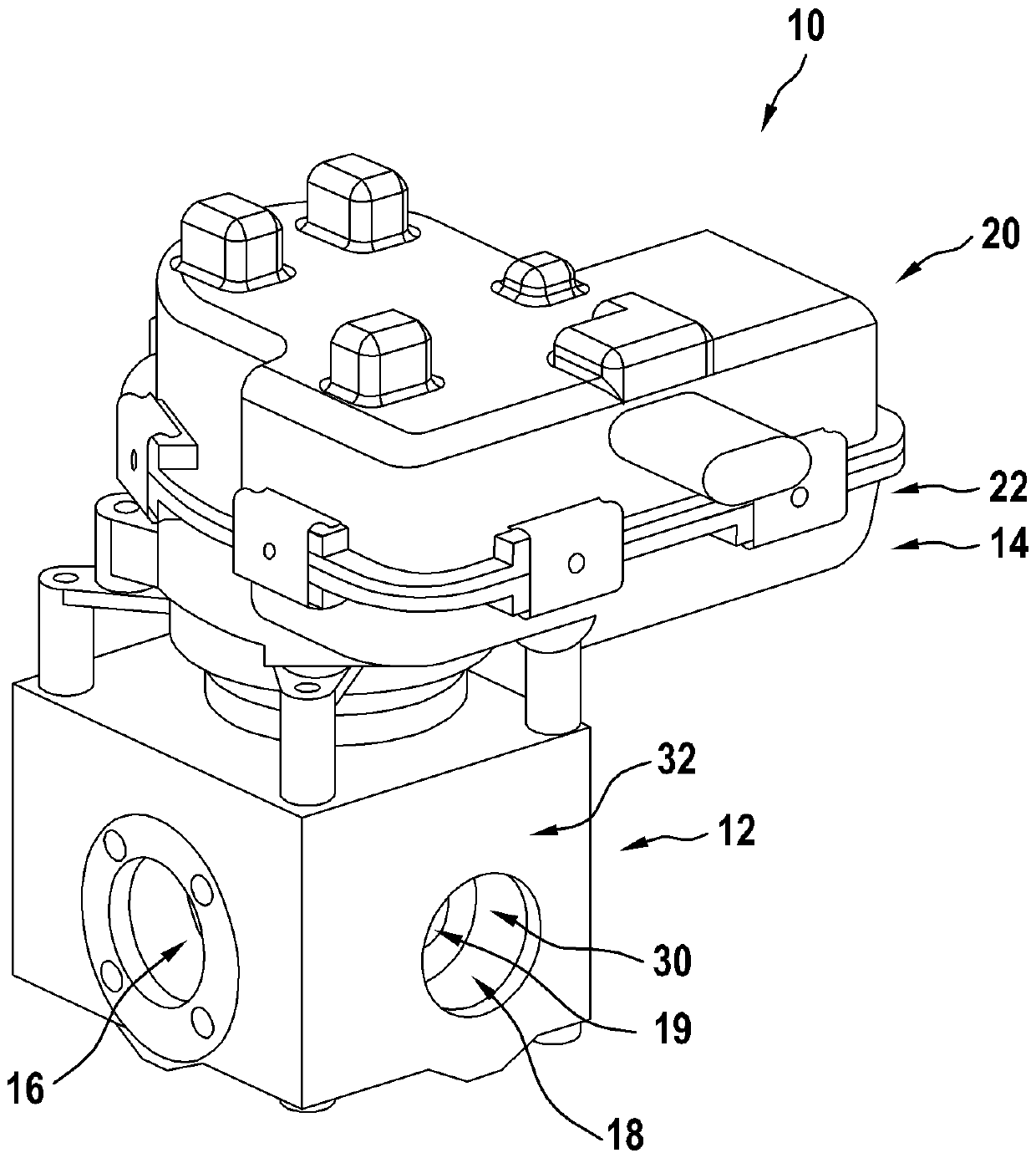
[0015] In these figures, the same parts have the same reference numerals. figure 1 An embodiment of a valve 10 according to the prior art is shown. Such as figure 1 It can be clearly seen that the valve has a valve element housing 12 and a further housing 14 arranged on the valve element housing. The valve member is designed to be movable, in particular rotatable relative to the valve member housing 12 . In particular, the valve means is arranged inside the valve means housing 12 . Furthermore, the valve device housing 12 has a flow region 19 through which a fluid flows. as in figure 1 It can be seen in the figure that the valve device housing has at least two first openings 16 and 18 which form an inlet or an outlet for the fluid in the valve device housing 12 .

[0016] Such as figure 1 It can clearly be seen in FIG. 1 that a second housing element, which is designed as the actuator housing of the valve 10 , is arranged on the valve component housing 12 . According to...


PUM


Abstract

The invention relates to a valve, in particular an expansion valve, for controlling a fluid flow, comprising a valve device housing and at least one valve device movably arranged in the valve device housing. According to the invention, at least one housing part of the valve device housing has a plastic body with a diffusion-blocking barrier layer, which contains metal.

Description

technical field [0001] The present invention relates to a valve for controlling fluid flow. Background technique [0002] In an expansion valve, the fluid is present at least partially in a gaseous phase, wherein high pressures generally exist in the range of 1-30 bar and briefly reach 100 bar. Expansion valves are known from the prior art, in which the valve element housing is designed as a valve block made of aluminum, which is designed essentially gas-tight under the thermodynamic conditions prevailing in the expansion valve. However, such valve element housings made of aluminum are expensive, since they are complicated to manufacture and must be post-processed in some cases. Furthermore, the aluminum block housing is very heavy due to its size and material selection. Contents of the invention [0003] The invention relates to a valve, in particular an expansion valve, for controlling a fluid flow, with a valve element housing and at least one valve element arranged d...

Claims


Application Information

Patent Timeline
Patent Type & Authority Applications(China)
IPC IPC(8): F16K27/00F16K11/00
CPCF16K27/00F16K11/00F25B41/35Y02B30/70
Inventor T.霍尔策
Owner ROBERT BOSCH GMBH
Learn More