


Quick Research
Generate reliable direction feasibility study reports for your R&D in just a few steps.

Technical Q&A
Discover and master advanced knowledge NOW. Basics, ideas, possibilities, all at once.

Find Solutions
As an expert in R&D theories, this can generate solutions to your technical problems instantly.

Evaluate Feasibility
Analyze your overall solution with one click, know your potential R&D risks in advance.

Monitor Landscape
Get weekly tech updates, stay abreast of the latest tech innovations and key insights.
Convenient-to-use multifunctional grinding device for mold production
A multi-functional, mold-based technology, applied in grinding drives, grinding/polishing safety devices, grinders, etc., can solve problems such as affecting users' experience with grinding devices, single-function grinding devices, and inability to recover debris, etc. Rich functions, convenient scope of application, and the effect of improving user experience
- Summary
- Abstract
- Description
- Claims
- Application Information
AI Technical Summary
Problems solved by technology
Method used
Image


Examples
Embodiment 1
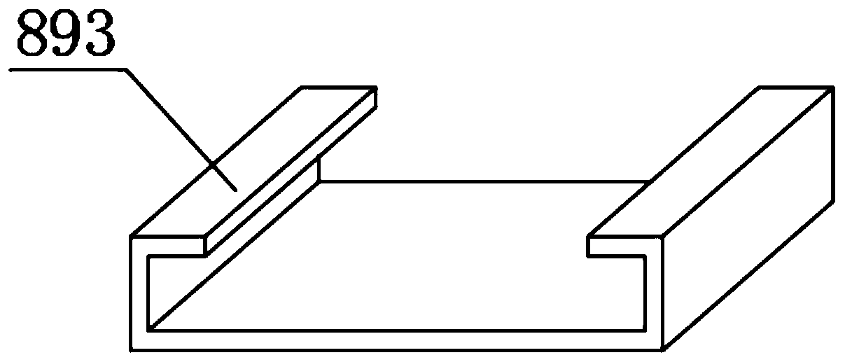
[0024] see Figure 1-Figure 4 , the present invention provides a technical solution: an easy-to-use multifunctional grinding device for mold production, including a first support plate 5, a grinding mechanism 8 is arranged above the first support plate 5, and the grinding mechanism 8 includes a second support plate 894, the two ends of the upper surface of the first support plate 5 are welded with the adjustable support rod 6 corresponding to the second support plate 894, the top of the adjustable support rod 6 is provided with the adjusting bolt 7, and the bottom of the second support plate 894 is provided with The limiting member 893, the lower surface of the second support plate 894 is provided with a limiting slide rail 88 corresponding to the limiting member 893, the limiting member 893 can slide along the limiting slide rail 88, and the bottom of the limiting member 893 is arranged There is a second hydraulic cylinder 892, a limit bearing 891 is provided at the connectio...
Embodiment 2
[0032] On the basis of Embodiment 1, in order to make it more convenient for users to fix the mold, in this embodiment, preferably, the bottom end of the adjustable support rod 6 is provided with a fixing mechanism 9, and the fixing mechanism 9 includes a third hydraulic cylinder 96, One end of the third hydraulic cylinder 96 is welded with a limit sleeve 97 corresponding to the adjustable support rod 6, and one side of the limit sleeve 97 is provided with a second limit bolt 98 corresponding to the adjustable support rod 6, The other end of the third hydraulic cylinder 96 is welded with a fourth limiting plate 95;
[0033] In order to make the application range of the fixing mechanism 9 wider, in this embodiment, preferably, one side of the fourth limiting plate 95 is provided with a fixing plate 92, and the two ends of the fixing plate 92 are welded with the fourth limiting plate 95. Corresponding to the second limit rod 91, one end of the second limit rod 91 is provided wit...
PUM
 Abstract
Description
Claims
Application Information
 - R&D Engineer
- R&D Manager
- IP Professional
- Industry Leading Data Capabilities
- Powerful AI technology
- Patent DNA Extraction
Browse by: Latest US Patents, China's latest patents, Technical Efficacy Thesaurus, Application Domain, Technology Topic, Popular Technical Reports.
© 2024 PatSnap. All rights reserved.Legal|Privacy policy|Modern Slavery Act Transparency Statement|Sitemap|About US| Contact US: help@patsnap.com