
Contact type evaporation system

An evaporation system and contact technology, applied in evaporation, evaporator accessories, chemical instruments and methods, etc., can solve the problems of accelerated scaling process, blockage of flow channels between evaporation tubes or plates, and large investment costs.

Inactive Publication Date: 2020-04-03
韩林辰 +1
View PDF5 Cites 0 Cited by
  • Summary
  • Abstract
  • Description
  • Claims
  • Application Information

AI Technical Summary

Problems solved by technology

This method avoids direct contact between the two, can avoid mutual pollution, and has high evaporation efficiency, but this type of evaporation method also has significant disadvantages: (1) The temperature of the non-contact evaporation heat source is relatively high, generally above the boiling point of water, Usually, a high-quality steam heat source is required; (2) The material of the evaporation surface of the equipment must be a metal material with good thermal conductivity, because the liquid may contain corrosive substances, such as oxidizing ions (chloride ions, fluoride ions, etc.), strong acids, Strong alkali requires high-quality stainless steel or higher-grade metal materials, such as titanium alloy or Hastelloy, and the equipment investment cost is huge; (3) heat transfer (heat transfer) and mass transfer (liquid evaporation) in the evaporation process ) all occur on the same surface. This evaporation method is very easy to scale on the surface. When the content of evaporated liquid organic matter is high, the scaling process will be accelerated, and in severe cases, it will cause blockage of the evaporation tube or the flow channel between the plates.

Method used


Image

  • Contact type evaporation system
  • Contact type evaporation system
  • Contact type evaporation system

Examples


Embodiment 1

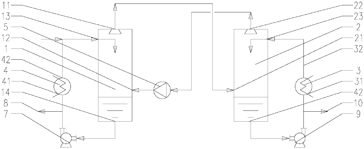
[0144] Take the treatment liquid, such as figure 1 As shown, the treatment liquid is processed through the contact evaporation system in the present invention. First, the treatment liquid flows into the pipeline where the heating heat exchanger is located in the pipeline of the heating cycle under the action of the first circulation pump, and is mixed with the evaporation concentrate. Finally, heat treatment is carried out through the heating heat exchanger. According to the properties of the treatment liquid, the temperature of the cold side is increased, the concentration of the heated treatment liquid increases, and the temperature of the treatment liquid increases. Then the heated treatment liquid is 0.01-500m 3 The flow rate of / h enters the evaporator through the liquid inlet of the treatment liquid. At the same time, the carrier gas is input into the evaporator through the fan at a flow rate of 1-1000000kg / h through the carrier gas inlet. The carrier gas is air or inert...

Embodiment 2

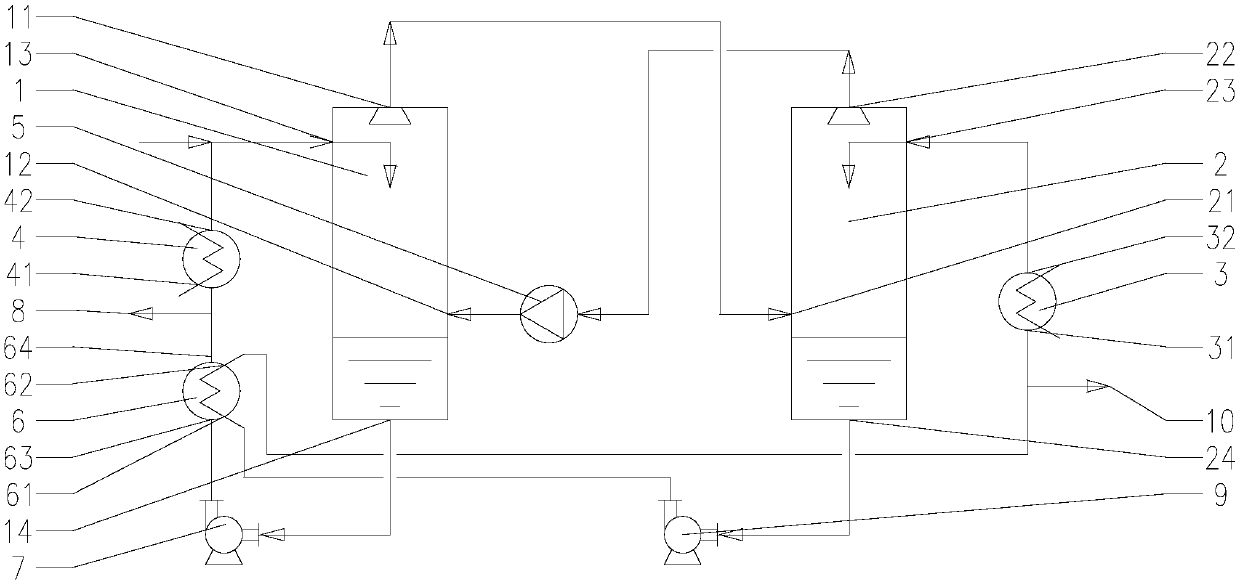
[0147] Take the treatment liquid, such as figure 2As shown, the treatment liquid is processed through the contact evaporation system in the present invention. First, the treatment liquid flows into the pipeline where the heating heat exchanger is located in the pipeline of the heating cycle under the action of the first circulation pump, and is mixed with the evaporation concentrate. Finally, heat treatment is carried out through the heating heat exchanger, and at the same time, the heat released by the condensate is absorbed by the heat recovery heat exchanger to provide heat for further heat treatment. According to the properties of the treatment liquid, increasing the temperature of the cold side increases the concentration of the treatment liquid after heating and increases the temperature of the treatment liquid. Then the heated treatment liquid is heated at 1-100m 3 The flow rate of / h enters the evaporator through the liquid inlet of the treatment liquid. At the same ...

Embodiment 3

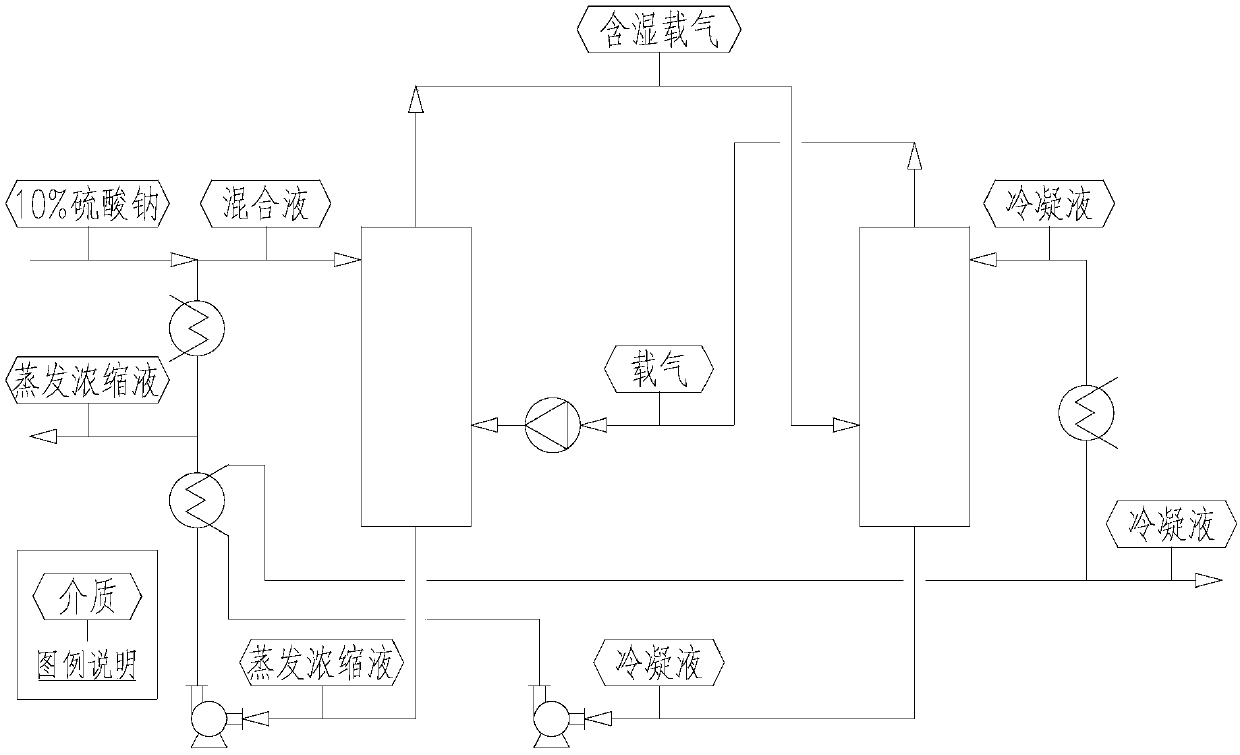
[0150] Take the treatment liquid, such as image 3 As shown, the treatment liquid is a 10wt% sodium sulfate aqueous solution, and the temperature of the treatment liquid is 10-30°C. The treatment liquid is processed through the contact evaporation system in the present invention. First, the treatment liquid flows into the pipeline where the heating heat exchanger is located in the pipeline of the heating cycle under the action of the first circulation pump, and is mixed with the evaporation concentrate to form a mixed The liquid is heated through the heating heat exchanger, and at the same time, the heat released by the condensate is absorbed by the heat recovery heat exchanger, and then the heat is released to further provide heat for the heating treatment. According to the properties of the treatment liquid, the temperature of the cold side is raised from 10-30°C to 40-100°C. Then the heated treatment liquid is heated at 1-100m 3 The flow rate of / h enters the evaporator t...


PUM


Abstract

The invention provides a contact type evaporation system, which comprises an evaporator, a condenser, a heating heat exchanger and a cooling heat exchanger, wherein heating circulation is formed between the evaporator and the heating heat exchanger through a pipeline so as to make a treatment liquid be mixed with carrier gas in the evaporator to form moisture-containing carrier gas after being heated by the heating heat exchanger, the evaporator is communicated with the condenser through a pipeline so as to input the moisture-containing carrier gas into the condenser from the evaporator, and cooling circulation is formed between the condenser and the cooling heat exchanger through a pipeline so as to make the moisture-containing carrier gas be separated into carrier gas and condensate after being cooled by condensate water generated by the cooling heat exchanger in the condenser. The invention further provides a contact type evaporation method. The contact type evaporation system provided by the invention has the characteristics that the quality of a required heat source is low, the material price of evaporation equipment is low, and mass transfer and heat transfer positions can beseparated so as to significantly prevent scaling.

Description

technical field [0001] The invention belongs to the technical field of liquid treatment and relates to a contact evaporation system. Background technique [0002] Evaporation is the phase change process of a substance from a liquid state to a gaseous state. The liquid that often needs to be evaporated in industry can be a single solvent, liquid organic matter or water; it can also be a mixture of organic matter and water; it can also be a saline solution or a saline organic liquid. During the evaporation process of a liquid with water as the main component, water and light organic matter tend to undergo a phase change and leave the system in the form of vapor, while heavy organic matter, salts or suspended matter in the liquid remain in the liquid or crystallization. Conventional evaporation equipment includes evaporation kettle, single (multiple) effect evaporation device, reboiler or mechanical vapor compression evaporator (MVR), etc., and the heating medium of these equ...

Claims


Application Information

Patent Timeline
Patent Type & Authority Applications(China)
IPC IPC(8): B01D1/00B01D1/30
CPCB01D1/00B01D1/30
Inventor 韩林辰崔海涛
Owner 韩林辰
Learn More