Automatic switch-off mechanism
A technology of automatic disconnection and switching, which is applied to the power device, electric switch, contact operating mechanism and other directions inside the switch, which can solve the problems of inverter burnout, fire, and increase the safety risk of operators, so as to reduce the space , Improve the effect of security
- Summary
- Abstract
- Description
- Claims
- Application Information
AI Technical Summary
Problems solved by technology
Method used
Image
Examples
Embodiment 1
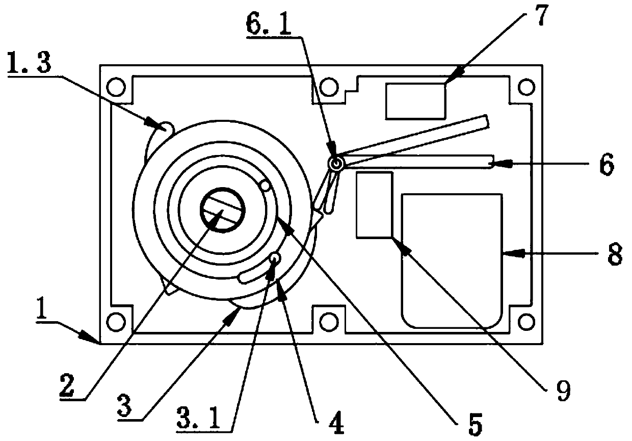
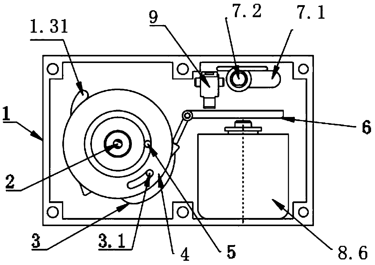
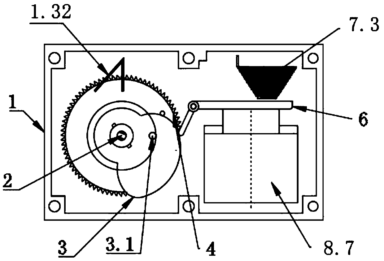
[0029] combined with figure 1 , 2 , 6-9, a switch automatic disconnection mechanism, including a housing 1, the interior of the housing 1 is hollow, and the housing 1 is provided with a main shaft 2, a cam 3 sleeved on the main shaft 2, a sleeve The rotating ratchet 4 arranged on the main shaft 2, the torsion spring 5 sleeved on the main shaft 2, the control ratchet 6 cooperating with the rotating ratchet 4, and the limit mechanism 1.3 for limiting the rotation range of the cam 3, the The main shaft 2 runs through the housing 1 and is integrated with the switch shaft. The cam 3 is fixedly connected to the main shaft 2. A guide pin 3.1 is provided on one end surface of the cam 3. The rotating ratchet 4 is arranged on the cam 3. One side of the guide pin 3.1 is provided and matched with the hole of the main shaft 2, and the torsion spring 5 is arranged on one side of the rotating ratchet 4 so that the torsion spring 5 is in a tightened state when the main shaft 2 rotates clockw...
Embodiment 2
[0036] combined with figure 1 , 3 , 7-9, compared with Embodiment 1, the difference between this embodiment and Embodiment 1 is:
[0037] The limiting mechanism 1.3 is a brake shrapnel 1.31, one end of the torsion spring 5 is connected to the housing and the other end is fixedly connected to the cam 3, the main shaft 2 is fixedly connected to the rotating ratchet 4 pins, the The reset mechanism 7 is a reset spring 7.3, and the trigger mechanism 8 is an impact electromagnet 8.7.
Embodiment 3
[0039] combined with figure 1 , 4 , 7-9, compared with Embodiment 1, the difference between this embodiment and Embodiment 1 is:
[0040] The limiting mechanism 1.3 is an oblong protrusion 1.31, the main shaft 2 is gear-connected to the rotating ratchet 4, one end of the torsion spring 5 is connected to the housing and the other end is fixedly connected to the main shaft 2, The reset mechanism 7 is a reset spring 7.3. The trigger mechanism 8 includes a motor 8.1, a trigger cam 8.2 connected to the motor 8.1, and a push rod 8.3 matched with the trigger cam 8.2. The frame 8.5 of the rod 8.3, the frame 8.5 is fixedly connected to the housing 1, and the trigger spring 8.4 sleeved on the push rod 8.3 is arranged inside, and the micro switch 9 is also provided in the housing 1, The micro switch 9 is arranged on the side of the trigger mechanism 8 close to the locking plate 6.3.
PUM
 Abstract
Description
Claims
Application Information
 - R&D
- Intellectual Property
- Life Sciences
- Materials
- Tech Scout
- Unparalleled Data Quality
- Higher Quality Content
- 60% Fewer Hallucinations
Browse by: Latest US Patents, China's latest patents, Technical Efficacy Thesaurus, Application Domain, Technology Topic, Popular Technical Reports.
© 2025 PatSnap. All rights reserved.Legal|Privacy policy|Modern Slavery Act Transparency Statement|Sitemap|About US| Contact US: help@patsnap.com


