
Generator output voltage wiring device and control protection method thereof

A wiring device and output voltage technology, which is applied in the direction of controlling generators, emergency protection circuit devices, controlling generators through magnetic field changes, etc., can solve the problems of stuck switch blades, easy burning, and overload current of generator windings. Short-circuit protection function Over-voltage protection function and other issues to achieve the effect of avoiding accidents and safety hazards

Active Publication Date: 2020-07-17
福州万舸动力设备有限公司
View PDF6 Cites 0 Cited by
  • Summary
  • Abstract
  • Description
  • Claims
  • Application Information

AI Technical Summary

Problems solved by technology

However, due to the limited space in the generator wiring box and the need for professionals to manually change the wiring mode, it cannot meet the simple and fast operation requirements of general users
In the later upgrade, the diverter switch and contactor switch were used instead of manually changing the wiring. Although the output voltage of the generator was automatically switched, due to such switches as the diverter switch and contactor, the generator winding load current overload and short circuit were not available. Protection function and overvoltage protection function. At the same time, the arc generated when these types of switches are used for a long time and frequently switched is easy to burn or jam the switch edge, resulting in accidents and safety hazards such as burning of the inner winding of the generator. However, there is no one on the market at present. An effective solution and control protection method

Method used


Image

  • Generator output voltage wiring device and control protection method thereof
  • Generator output voltage wiring device and control protection method thereof
  • Generator output voltage wiring device and control protection method thereof

Examples


Embodiment Construction

[0057] The present invention will be described in detail below in conjunction with specific embodiments and accompanying drawings.

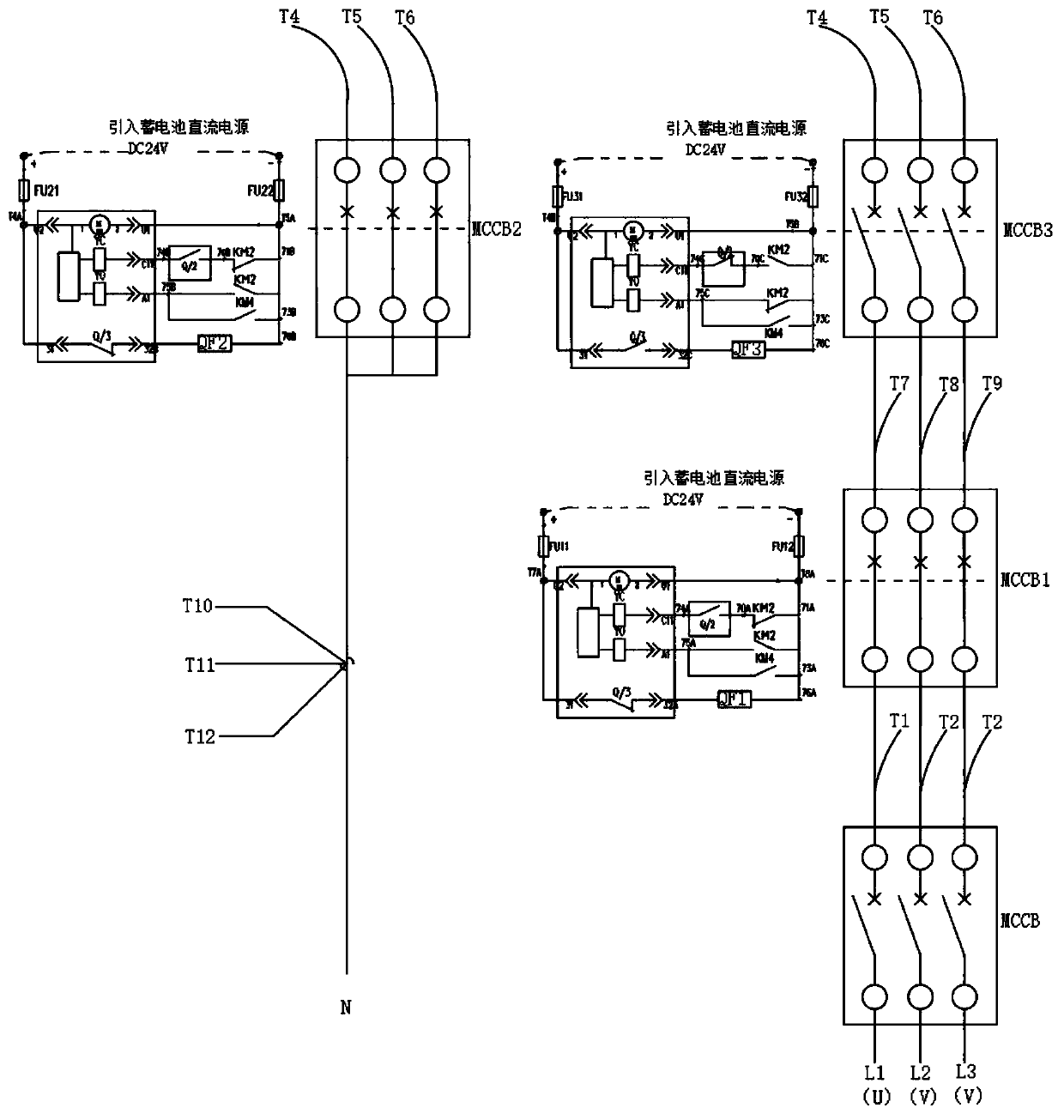
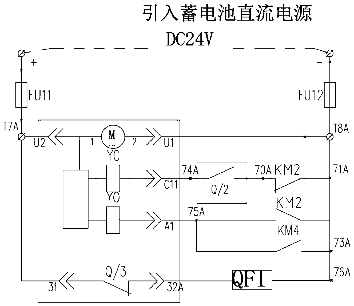
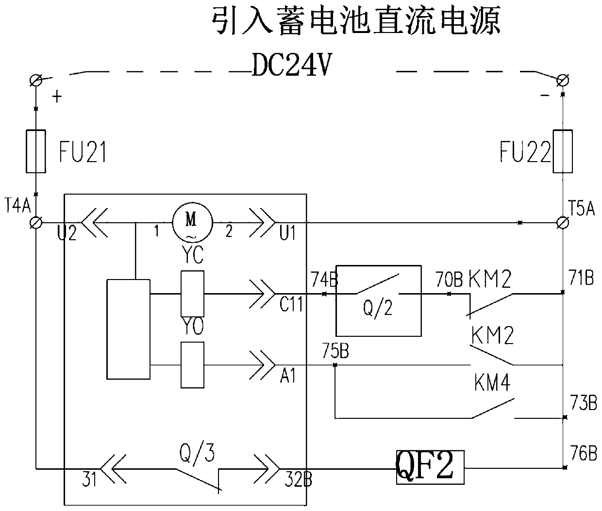
[0058] see figure 1 , figure 2 , image 3 , Figure 4 , Figure 5 , this embodiment provides a generator output voltage wiring device, including molded case circuit breaker MCCB1, molded case circuit breaker MCCB2, molded case circuit breaker MCCB3, DC24V relay KM2, DC24V relay KM4, DC24V relay QF1, DC24V relay QF2, DC24V Relay QF3, genset controller DSE7320 and genset load output circuit breaker MCCB; molded case circuit breaker MCCB1, molded case circuit breaker MCCB2 and molded case circuit breaker MCCB3 all have built-in electric execution closing and opening mechanism M~ and circuit breaker closing coil YC and circuit breaker opening coil YO also have built-in DC24V relay QF1, DC24V relay QF2, DC24V relay QF3, and closing feedback signal auxiliary contact Q / 1, closing feedback signal auxiliary contact Q / 2, respectively. Closing feedbac...


PUM


Abstract

The invention relates to the technical field of generators, in particular to a generator output voltage wiring device and a control protection method thereof. The wiring device comprises three circuitbreakers with built-in electric switching-on and switching-off mechanisms, a plurality of relays, a generator set controller and a total output circuit breaker. The generator set controller outputs acontrol signal. According to the utility model, the three circuit breakers are controlled to be internally provided with electric switching-on and switching-off mechanisms, and the switching-on and switching-off of the three circuit breakers are automatically coordinated and controlled in a unified manner through an electric interlocking control relay mode, thereby achieving the automatic switching of the internal winding of the generator set between a parallel star and a series star, and achieving the output of different voltages. According to the invention, automatic switching between parallel star-shaped and series star-shaped output voltages of the generator can be fully automatically realized, and accidents such as burnout of the generator and potential safety hazards are safely andcomprehensively avoided.

Description

technical field [0001] The invention relates to the technical field of generators, in particular to a generator output voltage wiring device and a control and protection method thereof. Background technique [0002] Diesel generator sets are widely used in today's international society as backup and main power generation. In the international construction machinery and power equipment rental market, especially in the field of industrial electricity, because industrial equipment requires power supplies of different voltages (such as three-phase 230V and three-phase 460V in the Philippines, and three-phase 220V and three-phase 460V in American countries and regions) Three-phase 440V ~ 480V), it is often necessary to change the output voltage of the generator in order to provide a suitable and stable voltage power supply for the equipment. [0003] In order to change the output voltage of the generator, in the early days of the generator set industry, most of them used the met...

Claims


Application Information

Patent Timeline
Patent Type & Authority Applications(China)
IPC IPC(8): H02P9/14H02H7/06H02P101/25
CPCH02P9/14H02H7/06H02P2101/25
Inventor 吴挺辉
Owner 福州万舸动力设备有限公司
Learn More