
Vertical electroplating conveying device

A conveying device, vertical technology, applied in the field of transmission, can solve the problems of large external dimension and axial force, large vibration, impact and noise, and inability to maintain accurate transmission ratio, etc., to achieve compact structure, large load capacity, less stressful effect

Pending Publication Date: 2020-03-31
王周峰
View PDF0 Cites 2 Cited by
  • Summary
  • Abstract
  • Description
  • Claims
  • Application Information

AI Technical Summary

Problems solved by technology

[0002] At present, the common transmission methods are: chain transmission, belt transmission, steel belt transmission and gear transmission. However, the three transmission methods have certain shortcomings. The disadvantages of the chain transmission method are: large noise, shock and vibration, and high requirements for installation accuracy. After the hinge of the chain is worn, the pitch becomes larger and causes shedding;
[0003] Disadvantages of the belt drive mode: relying on frictional force transmission, high power cannot be transmitted; there is slippage in the transmission, the accurate transmission ratio cannot be maintained, and the efficiency is low; when the same large circular force is transmitted, the external dimension and the force on the shaft Large; belt wears out faster and has a shorter lifespan
[0004] Disadvantages of steel belt transmission: short life, not durable, prone to slipping, etc.
[0005] Disadvantages of gear transmission mode: large vibration, impact and noise during operation, and dynamic load; no overload protection; high gear cutting accuracy and high cost

Method used


Image

  • Vertical electroplating conveying device
  • Vertical electroplating conveying device
  • Vertical electroplating conveying device

Examples


Embodiment Construction

[0051] The present invention will be described in further detail below in conjunction with the embodiments and accompanying drawings, so that those skilled in the art can implement it with reference to the description.

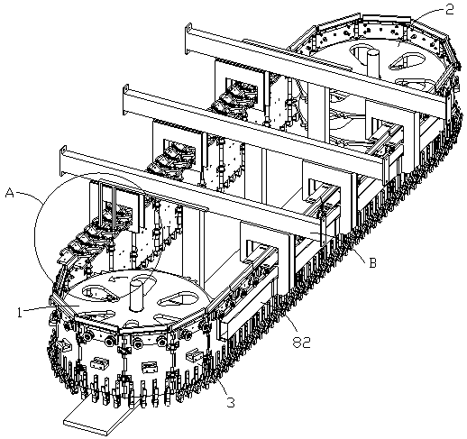
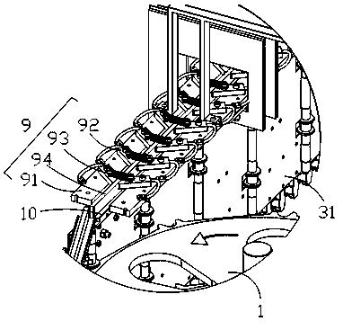
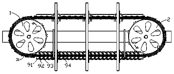
[0052] see Figure 1-7As shown, the embodiment of the present invention discloses a vertical electroplating conveying device, including a driving sprocket 1, a driven sprocket 2 and a conveyor belt 3, the conveyor belt 3 includes a plurality of chain plates 31 connected in series by hinges, and the driving sprocket 1 and the outer edge of the driven sprocket 2 are respectively evenly distributed with ten pairs of locking teeth 4, and the chain plate 31 is provided with locking holes 311. When the chain plate 31 passes through the driving sprocket 1 or the driven sprocket 2, the locking teeth 4 Snap into the clamping hole 311 so that the chain plate 31 rotates under the rotation of the driving sprocket 1 or the driven sprocket 2, the conveyor belt 3 is perpendi...


PUM


Abstract

The invention discloses a vertical electroplating conveying device. The device comprises a driving sprocket, a driven sprocket and a conveying belt, the conveying belt is perpendicular to the horizontal plane and comprises a plurality of chain plates which are connected in series in a hinged mode, each chain plate is provided with a supporting piece used for hanging a product to be conveyed, pairsof clamping teeth are evenly distributed on the outer edge of the driving sprocket and the outer edge of the driven sprocket respectively, each chain plate is provided with clamping holes, and when the chain plate passes the driving or driven sprocket, the clamping teeth are clamped into the clamping holes so that the chain plate can rotate under rotation of the driving or driven sprocket. The vertical chain plate conveying device provided by the invention can be used for hanging electroplated products for conveying, is long in conveying distance, stable in conveying, low in noise, capable ofrunning at a low speed and a medium-high speed, free of slipping and shaking, large in load capacity, low in maintenance cost, capable of adapting to various environments and wide in application range.

Description

technical field [0001] The invention relates to the field of transmission technology, in particular to a vertical electroplating conveying device. Background technique [0002] At present, the common transmission methods are: chain transmission, belt transmission, steel belt transmission and gear transmission. However, the three transmission methods have certain shortcomings. The disadvantages of the chain transmission method are: large noise, shock and vibration, and high requirements for installation accuracy. After the hinge of the chain is worn, the pitch becomes larger and causes shedding; [0003] Disadvantages of the belt drive mode: relying on frictional force transmission, high power cannot be transmitted; there is slippage in the transmission, the accurate transmission ratio cannot be maintained, and the efficiency is low; when the same large circular force is transmitted, the external dimension and the force on the shaft Large; belt wears out faster and has a sho...

Claims


Application Information

Patent Timeline
Patent Type & Authority Applications(China)
IPC IPC(8): B65G23/06B65G17/20B65G17/38B65G21/22C25D17/06
CPCB65G23/06B65G17/20B65G17/38B65G21/22C25D17/06
Inventor 王周峰
Owner 王周峰
Learn More