
Mechanical arm for high-speed carrying

A manipulator, high-speed technology, applied in the direction of manipulators, program-controlled manipulators, conveyor objects, etc., can solve the problems of limited cylinder stroke, low work efficiency, short service life, etc., to increase transmission distance, prolong service life, and strong carrying capacity Effect

Active Publication Date: 2015-05-06
苏州凯蒂亚半导体制造设备有限公司
View PDF7 Cites 0 Cited by
  • Summary
  • Abstract
  • Description
  • Claims
  • Application Information

AI Technical Summary

Problems solved by technology

[0003] The conveying manipulators in the prior art are generally equipped with cylinders to realize the transmission of items, but the stroke of the cylinder is limited, and it can only be transmitted in a short distance. Once the transmission distance increases, the cost of using the cylinder will increase greatly. Therefore, when long-distance transmission is required Synchronous belts are used when using, but due to possible slippage of the synchronous belt, belt slack, and conveying errors caused by belt elasticity, the items carried on the belt will deviate from the preset position during use and cannot be accurately transmitted. Increase, the distance deviation of the items conveyed by the synchronous belt will also increase
In addition, synchronous belt transmission also has the following disadvantages: the synchronous belt will wear out with the increase of use time, and its service life is short; the transmission speed is not high and the work efficiency is low; ), due to the low carrying capacity of the synchronous belt, it is impossible to transmit

Method used


Image

  • Mechanical arm for high-speed carrying
  • Mechanical arm for high-speed carrying
  • Mechanical arm for high-speed carrying

Examples


Embodiment

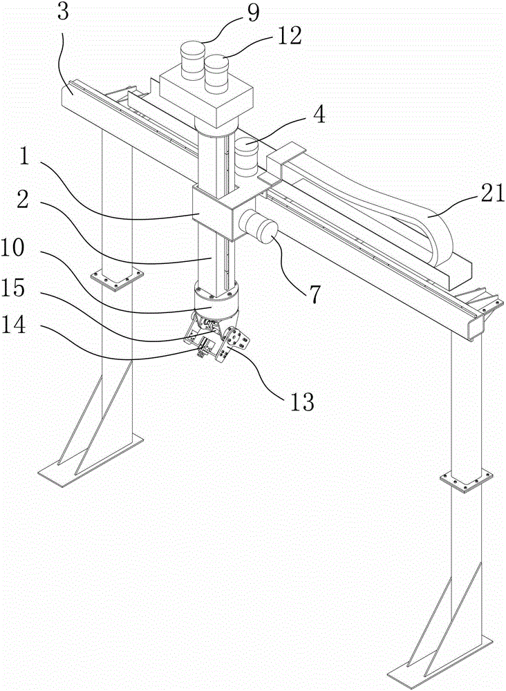
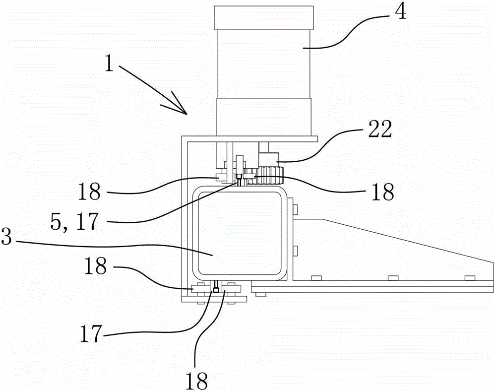
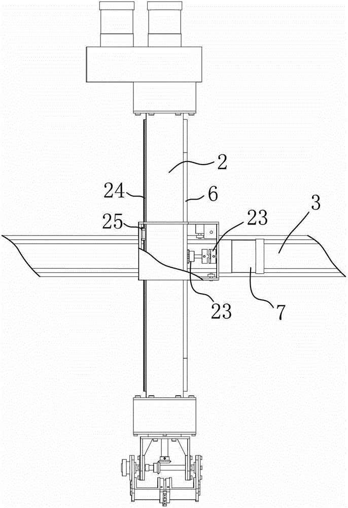
[0034] Example: see attached Figure 1~4 As shown, a high-speed transfer manipulator includes a frame, a transfer base 1, a robot arm 2, a grabbing part and a controller, wherein the frame has a beam 3 arranged along the horizontal direction.

[0035] The transfer seat 1 is horizontally slidably connected to the crossbeam 3, and a horizontal travel motor 4 is installed on the transfer seat 1. The crossbeam 3 is provided with a horizontal spur rack 5, and the horizontal travel motor 4 drives a gear and the horizontal spur gear. The strips 5 are meshed and matched so that the transfer seat 1 can move horizontally along the beam 3 to and fro. Specifically, a horizontal linear guide rail 17 is provided on the upper side and the lower side of the beam 3, and two sliders 25 are correspondingly provided on the transfer seat 1. These two sliders 25 are embedded and matched with the two horizontal linear guide rails 17, so that the transfer seat 1 can reciprocate horizontally along th...


PUM


Abstract

A mechanical arm for high-speed carrying is characterized by comprising a frame, a carrying seat, a mechanical arm, a gripping part and a controller. A crossbeam is horizontally disposed on the frame. The carrying seat is horizontally slidably connected with the crossbeam. The mechanical arm is vertically slidably connected with the carrying seat. The gripping part comprises horizontal rotary motor, a horizontal rotary support, a vertical rotary motor, a vertical rotary support and a gripper, wherein the horizontal rotary motor is used for driving a first vertical output shaft, the vertical rotary motor is used for driving a second vertical output shaft, and the horizontal rotary motor and the vertical rotary motor are mounted on the upper portion of the mechanical arm. An output end on the lower portion of the first vertical output shaft is fixedly connected with the horizontal rotary support. A horizontal shaft is supported on the horizontal rotary support through bearing rotation. An output end on the lower portion of the second vertical output shaft is in transmission connection with the horizontal shaft through a bevel gear mechanism. The horizontal shaft is further fixedly connected with the vertical rotary support. The gripper is disposed on the vertical rotary support. Automatic taking, automatic carrying and automatic discharge are achieved efficiently and accurately by the mechanical arm which is suitable for long-distance carrying of heavy objects.

Description

technical field [0001] The invention belongs to the technical field of mechanical automation equipment, and relates to a high-speed conveying manipulator, which is used for quickly and accurately picking and placing and conveying heavy goods. Background technique [0002] In industrialized and mechanized large-scale assembly line operations, due to the distance between different stations, it is often necessary to transport items from one station to another for processing, assembly, etc. The mechanism equipment that realizes this function is the transfer robot. The most basic function of the transfer manipulator is to realize the transfer of items in the assembly line between different stations. In the field of automobile manufacturing or other large-scale equipment manufacturing, it is often necessary to transfer heavy items (such as automobile engine crankshafts, camshafts, etc.), and it is necessary to accurately and efficiently transfer items from one station to another d...

Claims


Application Information

Patent Timeline
Patent Type & Authority Patents(China)
IPC IPC(8): B25J9/04B25J9/10B25J15/08B25J18/00B65G47/90
Inventor 顾石成陈华轩张乾峰刘翼杨定伟
Owner 苏州凯蒂亚半导体制造设备有限公司
Learn More