
An Anti-vibration DC Shunt for Impulse Current Measurement

A technology of inrush current and shunt, which is applied in the direction of test/measurement connectors, measuring devices, and current-only measurement, and can solve problems such as shunt vibration, hard equipment damage, and destruction

Active Publication Date: 2021-09-14
HENAN PROVINCE INST OF METROLOGY
View PDF0 Cites 0 Cited by
  • Summary
  • Abstract
  • Description
  • Claims
  • Application Information

AI Technical Summary

Problems solved by technology

However, during the measurement process, due to the different measurement environment, the shunt will be subjected to different degrees of vibration. For the existing DC shunt, the vibration is extremely damaging to the hard equipment, especially under the impact of high current , will be severely damaged and the economy will suffer

Method used


Image

  • An Anti-vibration DC Shunt for Impulse Current Measurement
  • An Anti-vibration DC Shunt for Impulse Current Measurement
  • An Anti-vibration DC Shunt for Impulse Current Measurement

Examples


Embodiment 1

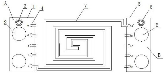
[0039] Such as figure 1 and Figure 4 The present invention includes a left connecting plate A, a right connecting plate B and a connecting body, and the connecting body connects the left connecting plate A and the right connecting plate B as a whole; the left connecting plate A includes a left conductive block body 1, a left connecting plate The left part of the conductive block body 1 is provided with a connecting hole 2 which is transparent up and down, the upper end surface of the left conductive block body 1 is provided with a left connecting bolt 3, and the right part of the left conductive block body 1 is provided with a row of concave grooves 4. The opening of the shaped groove cavity 4 faces the right end, and the left connecting plate A and the right connecting plate B have the same structure and are symmetrical; the right connecting plate B includes a right conductive block 5, and the right part of the right conductive block 5 is provided with a transparent The con...

Embodiment 2

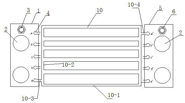
[0043] Such as figure 2 and Figure 4 As shown, the present invention includes a left connecting plate A, a right connecting plate B and a connecting body, and the connecting body connects the left connecting plate A and the right connecting plate B as one; the left connecting plate A includes a left conductive block body 1, a left connecting plate The left part of the conductive block 1 is provided with a connection hole 2 which is transparent up and down, and the connection hole 2 is used for connecting other configuration devices. The upper end surface of the left conductive block 1 is provided with a left connecting bolt 3, and the right part of the left conductive block 1 is provided with a row of concave grooves 4, the opening of the concave grooves 4 faces the right end, and the left connecting plate A and the right connecting plate The B structure is the same and symmetrical; the right connecting plate B includes a right conductive block 5, the right part of the righ...

Embodiment 3

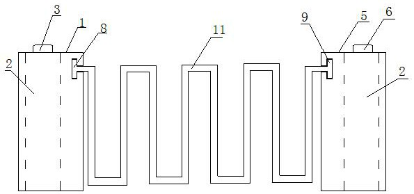
[0047] Such as image 3 and Figure 4 As shown, the present invention includes a left connecting plate A, a right connecting plate B and a connecting body, and the connecting body connects the left connecting plate A and the right connecting plate B as one; the left connecting plate A includes a left conductive block body 1, a left connecting plate The left part of the conductive block 1 is provided with a connection hole 2 which is transparent up and down, and the connection hole 2 is used for connecting other configuration devices. The upper end surface of the left conductive block 1 is provided with a left connecting bolt 3, and the right part of the left conductive block 1 is provided with a row of concave grooves 4, the opening of the concave grooves 4 faces the right end, and the left connecting plate A and the right connecting plate The B structure is the same and symmetrical; the right connecting plate B includes a right conductive block 5, the right part of the right...


PUM


Abstract

The invention discloses an anti-vibration DC shunt for measuring impulse current, which comprises a left connecting plate, a right connecting plate and a connecting body, the connecting body connects the left connecting plate and the right connecting plate as a whole; the left connecting plate includes a left conductive block body, the left part of the left conductive block is provided with up and down transparent connecting holes, the upper end of the left conductive block is provided with left connecting bolts, and the right part of the left conductive block is provided with a row of concave grooves, the concave grooves The opening faces the right end; the right connecting plate includes a right conductive block body, the right part of the right conductive block body is provided with a connection hole that is transparent up and down, the upper end surface of the right conductive block body is provided with a right connecting bolt, and the left part of the right conductive block body There is a row of concave grooves arranged up and down, and the opening of the concave grooves is towards the left end; the concave grooves of the left conductive block and the concave grooves of the right conductive block are arranged symmetrically; this device can effectively reduce vibration in the environment. The shunt is damaged by vibration, and by extending the connecting body, the resistance is enhanced to meet the impact measurement of the impact of large current.

Description

technical field [0001] The invention relates to the technical field of research on surge current measurement and calibration equipment, in particular to an anti-vibration DC shunt for surge current measurement. Background technique [0002] Impulse current is very important to the safety performance of electrical equipment, and it is used to test the ability of equipment to withstand transient current. The impulse current generator and its measurement system are the main equipment for simulating the impulse current. It is mainly used in power systems, communication systems, lightning protection component enterprises and railway systems, etc., to conduct electromagnetic compatibility tests of electrical equipment, arrester tests and lightning Impulse current withstand test. [0003] DC shunts are widely used in many circuit devices with direct current, especially circuit devices with large direct current and their testing. [0004] The structure of a general DC fixed-value ...

Claims


Application Information

Patent Timeline
Patent Type & Authority Patents(China)
IPC IPC(8): G01R15/14G01R19/00H01R11/01H01R11/09H01R4/26H01R4/48
CPCG01R15/146G01R19/0092H01R4/26H01R4/4809H01R4/4863H01R11/01H01R11/09H01R2201/20
Inventor 侯永辉周秉时贾红斌李岚孙军涛陈兵王赛爽张保健
Owner HENAN PROVINCE INST OF METROLOGY
Learn More