
Tensile creep test device and method for high-strength concrete

A high-strength concrete and test device technology, applied in the direction of measurement device, strength characteristics, and the use of stable tension/pressure to test material strength, etc., can solve problems affecting the authenticity of test data, limiting the tensile strength of glue, and destroying the overall It can overcome the uneven load application, overcome the instability of the measurement results, and reduce the difficulty of the test.

Pending Publication Date: 2020-03-27
SOUTHEAST UNIV
View PDF0 Cites 6 Cited by
  • Summary
  • Abstract
  • Description
  • Claims
  • Application Information

AI Technical Summary

Problems solved by technology

[0005] In terms of fixing the test piece to the equipment, the usual installation forms of the test piece have the following forms: 1) prefabricated anchors at both ends of the test piece, which destroys the integrity of the test piece; 2) anchors at both ends of the test piece Pasting the steel plate with glue, this form is limited by the tensile strength of the glue, especially when the test specimen is ultra-high performance concrete, it usually breaks at the glue joint, which affects the authenticity of the test data; 3) Fix it with clips The two ends of the specimen are not tightly clamped; 4) The dog bone specimen is used, and the clip is clamped at the contraction of both ends of the dog bone. This clamping form has stress concentration, and the ports are concentrated at the contact point, making the test The error becomes larger

Method used


Image

  • Tensile creep test device and method for high-strength concrete
  • Tensile creep test device and method for high-strength concrete
  • Tensile creep test device and method for high-strength concrete

Examples


Embodiment Construction

[0058] The present invention will be further explained below in conjunction with the accompanying drawings and specific embodiments.

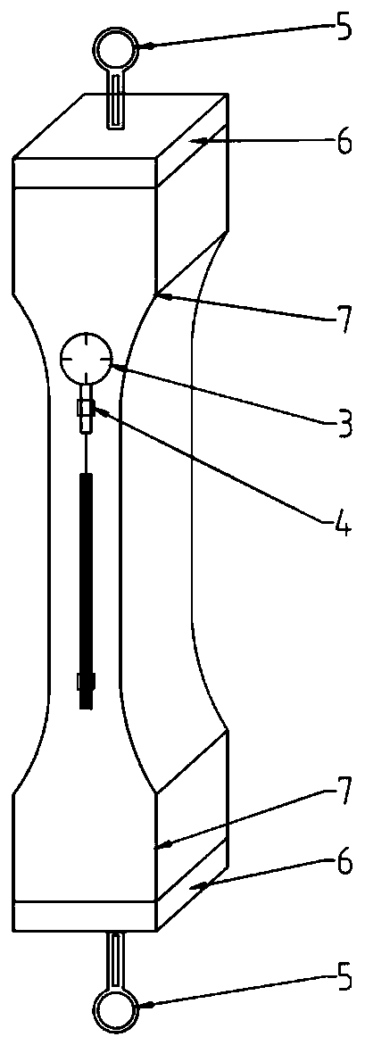
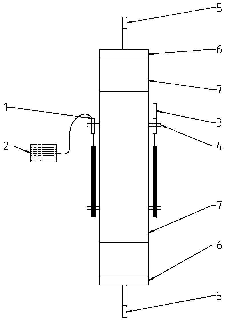
[0059] It can be seen from the accompanying drawings that a tensile creep test device for high-strength concrete includes a loading test device and a concrete test piece, the concrete test piece is connected to the loading test device, and one side of the concrete test piece is provided with A linear differential displacement sensor, the other side of the concrete test piece is provided with a dial indicator detector.

[0060] Described loading test device comprises top plate 9, base plate 19 and three threaded rods 12, and three threaded rods 12 upper ends are all fixedly connected on the top plate 9, and three threaded rods 12 lower ends are all fixedly connected on the base plate 19, and each threaded rod The middle part of 12 is provided with a sleeve 11, a force spring 14 and a stabilizing spring 16 sequentially from top to bottom, and a f...


PUM


Abstract

The invention relates to a tensile creep test device and method for high-strength concrete. A double-spring tensile creep device and a concrete test piece creep strain acquisition method are included.The double-layer spring tension creep device ensures the stability of the loading process and the later-stage load holding by utilizing double springs; a linear differential displacement sensor is arranged on one side of the concrete detection test piece, and a dial indicator detector is arranged on the other side of the concrete detection test piece; on the premise of ensuring that the difference between the two acquisition modes is within an error range, data points of sensors are used in the earlier stage, and the reading point of the dial indicator is used in the later period, and a logarithmic mapping method is used for mapping, so that the instantaneous deformation including elastic deformation in the initial loading stage can be displayed, the deformation in several years cannot beclose to the level, and the limitations that the value of the traditional strain acquisition method cannot be distinguished in a short time and the value of the traditional strain acquisition methodis positioned outside the graph are overcome; the test device and method have the characteristics of simple operation, low cost, reliable data and the like, and are suitable for carrying out tensile creep test for a long time.

Description

technical field [0001] The invention relates to a tensile creep test device and method for high-strength concrete, belonging to the field of concrete structures and materials. Background technique [0002] Creep is an important feature in the study of concrete properties. The traditional research is relatively mature on the creep of mature concrete under compression, but the research on the creep of concrete under tension, especially under the tension state of early concrete, is relatively mature. It is rare. After a large number of tests, it has been shown that whether concrete cracks depends not only on shrinkage, but also is largely affected by tensile creep. Therefore, the study of tensile creep is of great significance. The tensile creep test mainly includes three parts. , that is, the loading method, strain collection and specimen form. [0003] There are many loading methods used in tensile creep devices, but all of them have certain shortcomings. Lever loading is s...

Claims


Application Information

Patent Timeline
Patent Type & Authority Applications(China)
IPC IPC(8): G01N3/08G01N3/06
CPCG01N3/08G01N3/062G01N2203/0017G01N2203/0208G01N2203/0252G01N2203/0262G01N2203/0682G01N2203/0676
Inventor 刘加平吴义凯杨果许弟升
Owner SOUTHEAST UNIV
Learn More