Product fatigue limit detection equipment

A technology for testing equipment and fatigue limit, which is applied in the field of product fatigue limit testing equipment, can solve problems such as untrue displayed values, and achieve the effect of improving the precise control of products

Inactive Publication Date: 2020-03-27
普卓(湖北)装备科技有限公司
View PDF0 Cites 2 Cited by
  • Summary
  • Abstract
  • Description
  • Claims
  • Application Information

AI Technical Summary

Problems solved by technology

And the displayed value is not real

Method used


Image

  • Product fatigue limit detection equipment
  • Product fatigue limit detection equipment

Examples


Embodiment Construction

[0010] The following will clearly and completely describe the technical solutions in the embodiments of the present invention with reference to the accompanying drawings in the embodiments of the present invention. Obviously, the described embodiments are only some, not all, embodiments of the present invention.

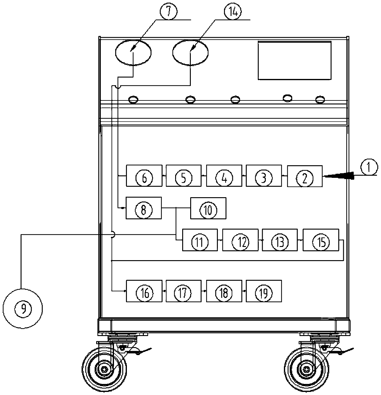
[0011] refer to Figure 1-2 , a product fatigue limit detection equipment, including air source 1, filter 2, pressure reducing valve 3, four two-position four-way solenoid valve 4, proportional flow valve 5, pressure sensor 6, digital display pressure gauge 7, the measured Product 8. Vacuum filter 9. Negative pressure proportional flow valve 10. Negative pressure digital display pressure gauge 11. Negative pressure sensor 12. Check valve 13. Vacuum pump 14. Stop valve 15. Muffler 16.

[0012] Air source 1, filter 2, pressure reducing valve 3, the first two-position four-way solenoid valve 4, proportional flow valve 5, pressure sensor 6, and digital display pressure g...


PUM


Abstract

According to product fatigue limit detection equipment, an air source, a filter, a pressure reducing valve, a first two-position four-way electromagnetic valve, a proportional flow valve, a pressuresensor and a digital display pressure gauge are connected in sequence, and the digital display pressure gauge is further connected with a detected product through a second two-position four-way electromagnetic valve. Meanwhile, a tested product and a third two-position four-way electromagnetic valve are respectively connected with the vacuum filter, and the vacuum filter, the fourth two-position four-way electromagnetic valve, the negative pressure proportional flow valve, the negative pressure digital display pressure gauge, the one-way valve, the vacuum pump, the stop valve and the silencerare sequentially connected.

Description

technical field [0001] The invention relates to the technical field of mechanical manufacturing, in particular to a product fatigue limit detection device. Background technique [0002] We know that the product fatigue limit detection equipment is a device that provides a power source through an air compressor and a vacuum pump, and sets the corresponding value to perform positive and negative pressure limits on the container, and fatigue cycle pulse pressure alternating testing equipment . It is widely used in manufacturing industry, industrial equipment, food and other industries. It can effectively detect product quality, understand the limit and life of the product in the use environment, so as to improve the effect of improving product quality and reducing engineering cost. Contents of the invention [0003] The purpose of the present invention is in order to solve when the process parameter of individual products is small. (Because the existing bench is used in no...

Claims


Application Information

Patent Timeline
Patent Type & Authority Applications(China)
IPC IPC(8): G01M13/00
CPCG01M13/00
Inventor 罗锋
Owner 普卓(湖北)装备科技有限公司
Why Eureka
Try Eureka