
Automatic decoking biomass semi-gasification combustion device

A combustion device and semi-gasification technology, applied in the direction of combustion methods, combustion equipment, solid fuel combustion, etc., can solve the problems of reduced boiler thermal efficiency, large smoke and dust emissions, and insufficient combustion, so as to improve combustion efficiency and oxygen supply Smooth, compact design effect

Pending Publication Date: 2020-03-27
河北益增新能源科技有限公司
View PDF0 Cites 1 Cited by
  • Summary
  • Abstract
  • Description
  • Claims
  • Application Information

AI Technical Summary

Problems solved by technology

[0003] The combustion method of the biomass reciprocating grate in the prior art is mostly the direct combustion type, that is, there is only one air in the combustion, the combustion is insufficient, the thermal efficiency is low, and the smoke emission is large, causing environmental pollution and great waste of energy
In the biomass burning device with a fixed grate, the fuel is dropped on the grate from the feed system and accumulated. Due to the uneven combustion of the fuel on the grate, the local temperature is too high, and coking often occurs, which makes the boiler The thermal efficiency is greatly reduced

Method used


Image

  • Automatic decoking biomass semi-gasification combustion device
  • Automatic decoking biomass semi-gasification combustion device
  • Automatic decoking biomass semi-gasification combustion device

Examples


Embodiment Construction

[0022] In order to make the purpose, features and advantages of the present invention more obvious and understandable, the technical solutions in the embodiments of the present invention will be clearly and completely described below in conjunction with the accompanying drawings in the embodiments of the present invention. Obviously, the following The described embodiments are only some, not all, embodiments of the present invention. Based on the embodiments of the present invention, all other embodiments obtained by persons of ordinary skill in the art without making creative efforts belong to the protection scope of the present invention.

[0023] The technical solutions of the present invention will be further described below in conjunction with the accompanying drawings and through specific implementation methods.

[0024] In the description of the present invention, it should be understood that the orientations or positional relationships indicated by the terms "upper", "...


PUM


Abstract

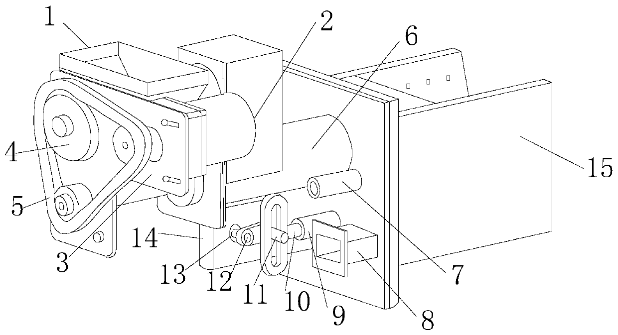
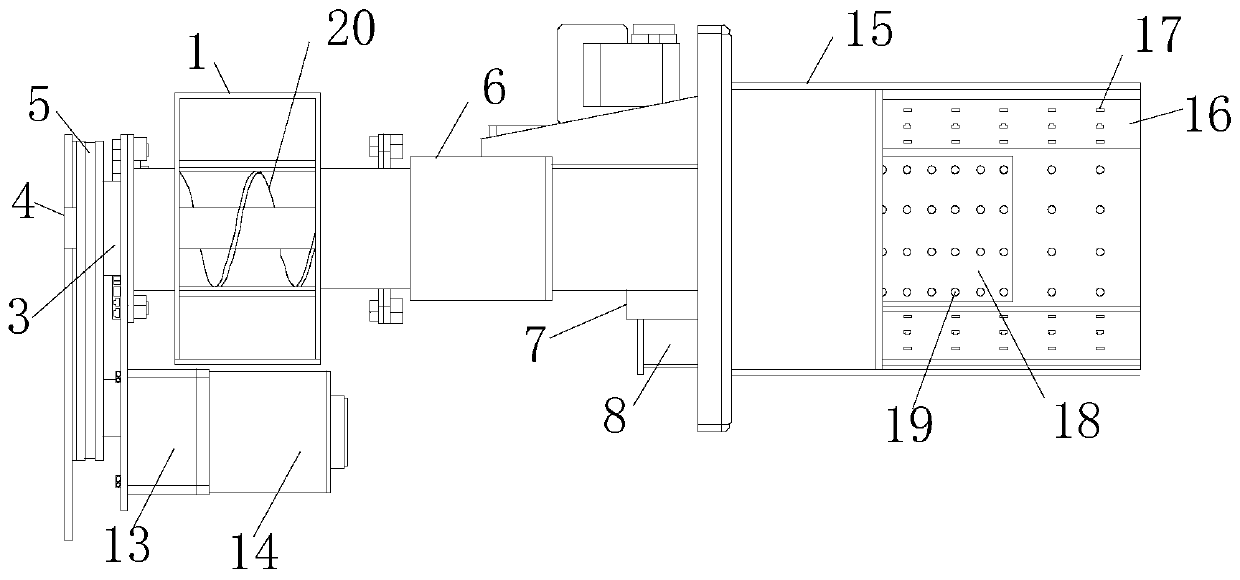
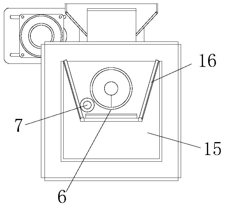
The invention discloses an automatic decoking biomass semi-gasification combustion device, which comprises a feeding port, a feeding motor, a feeding motor support, a chain wheel, a chain, a feeding pipe, an igniter pipe, an air blower interface, a connecting rod limiting pipe, a crank connecting rod mechanism, a cylindrical pin, an eccentric wheel, a reciprocating motor support, a reciprocating motor, a combustion chamber, a gasification wall, a secondary air hole, a reciprocating grate, a primary air hole, a feeding spiral conveyer, a connecting rod and a rail groove. The device is reasonable in structural design; air enters a cavity formed by the gasification wall and the combustion chamber from an air inlet and then goes out from air holes in the gasification wall and the reciprocatinggrate, so that secondary oxygen gasification combustion can be assisted to make biomass combustion more sufficient, and residues are reduced; the device is compact in structural design; and the reciprocating grate reciprocates at the bottom of the combustion chamber, and fuel can be conveyed to the middle of the combustion chamber, slag pushing and decoking are conducted regularly, so that oxygensupply of the combustion chamber is smooth, normal gasification combustion of the fuel is guaranteed, the combustion efficiency is improved, and practicability is high.

Description

technical field [0001] The invention relates to a combustion structure, in particular to an automatic decoking biomass semi-gasification combustion device, which belongs to the technical field of combustion devices. Background technique [0002] The burner is a general term for devices that make fuel and air spray out and combust in a certain way. Burners are divided into industrial burners, burners, civil burners, and special burners according to types and application fields. It is mostly made of corrosion-resistant and high-temperature-resistant materials such as stainless steel or metal titanium. The function of the burner is to atomize the sample by flame combustion. The atomized test solution enters the burner, and under the action of flame temperature and flame atmosphere, it undergoes drying, melting, evaporation, dissociation and other processes to produce a large number of ground state atoms, as well as some excited state atoms, ions and molecules. [0003] The c...

Claims


Application Information

Patent Timeline
Patent Type & Authority Applications(China)
IPC IPC(8): F23B30/10F23L9/00F23K3/00F23L5/02
CPCF23B30/10F23K3/00F23L5/02F23L9/00
Inventor 吴杰胡彬堵亚伟
Owner 河北益增新能源科技有限公司
Learn More