


Quick Research
Generate reliable direction feasibility study reports for your R&D in just a few steps.

Technical Q&A
Discover and master advanced knowledge NOW. Basics, ideas, possibilities, all at once.

Find Solutions
As an expert in R&D theories, this can generate solutions to your technical problems instantly.

Evaluate Feasibility
Analyze your overall solution with one click, know your potential R&D risks in advance.

Monitor Landscape
Get weekly tech updates, stay abreast of the latest tech innovations and key insights.
Nitrogen vaporization system and method for improving vaporization rate of nitrogen vaporizer
A carburetor and vaporization rate technology, applied in the field of machinery, can solve the problems of affecting the vaporization effect, easy formation of thin ice at the outlet end of the carburetor, etc., and achieve the effects of easy control, improved service life, and convenient floor space
- Summary
- Abstract
- Description
- Claims
- Application Information
AI Technical Summary
Problems solved by technology
Method used
Image

Examples
specific Embodiment 1
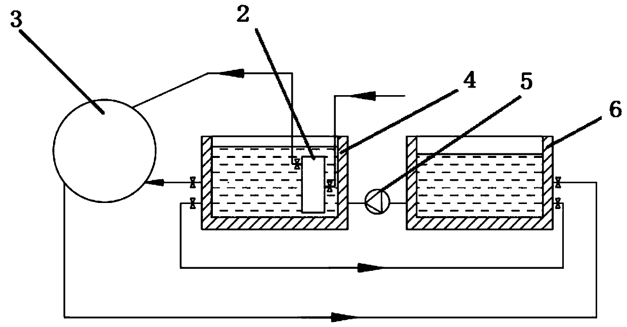
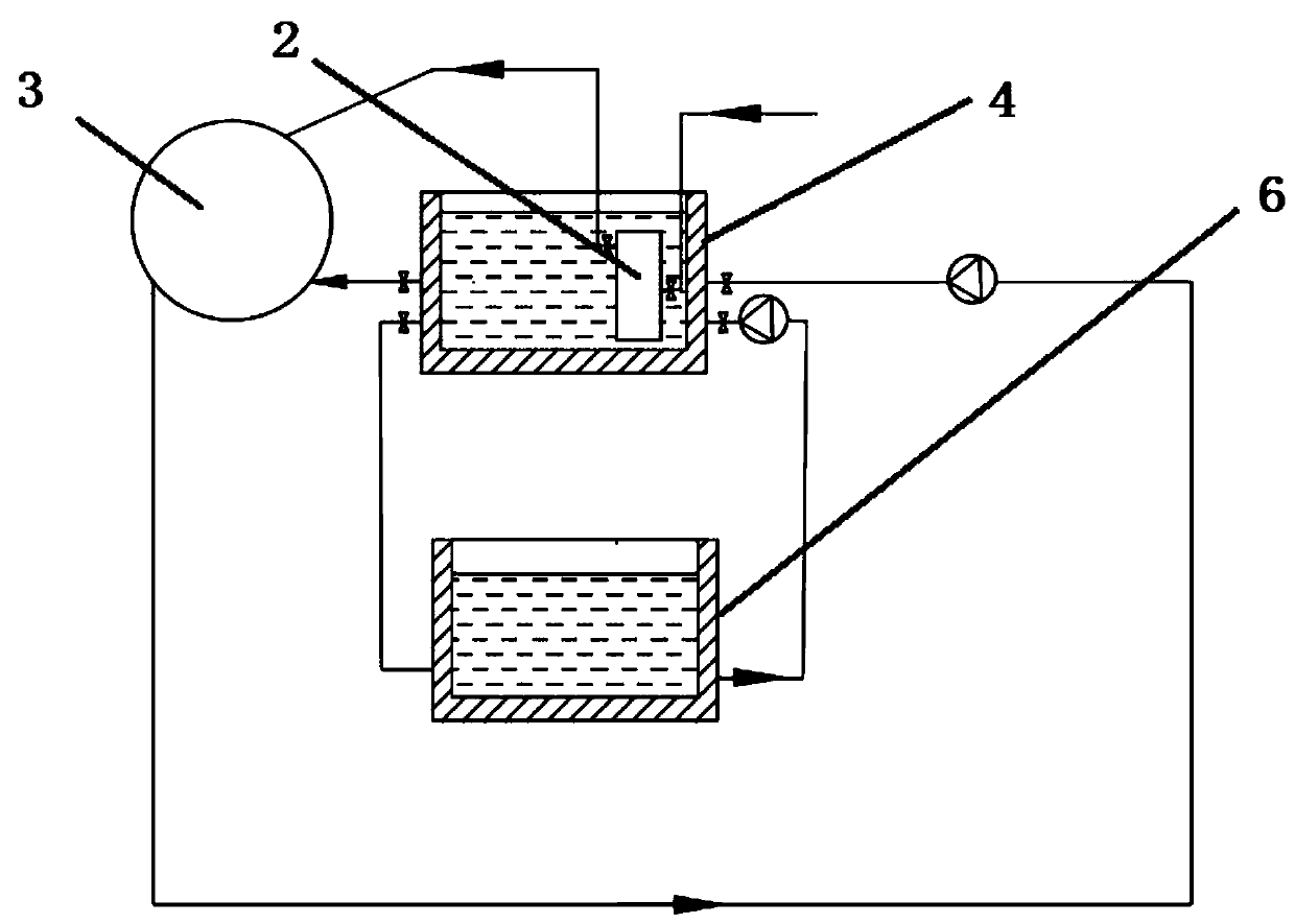
[0049] Specific embodiment 1, see figure 1 as well as figure 2 , a nitrogen vaporization system for improving the vaporization rate of a nitrogen vaporizer, comprising a nitrogen vaporization system, the nitrogen vaporization system includes a liquid nitrogen delivery pipeline, a vaporizer 2 and a nitrogen delivery pipeline sequentially connected along the diversion direction, and also includes a cooling water circulation system, the cooling water circulation system includes a cooling water tank 4, and the vaporizer 2 is immersed in the cooling water tank 4; the water outlet of the cooling water tank 4 is connected with the cooling water inlet of the pit furnace 3; Hot water circulation system, the hot water circulation system includes a hot water tank 6; the outlet of the hot water tank 6 is connected to the inlet of the cooling water tank 4 through the circulating water pump 5, and the inlet of the hot water tank 6 is connected to the cooling water tank 4 through a circulat...
specific Embodiment 2
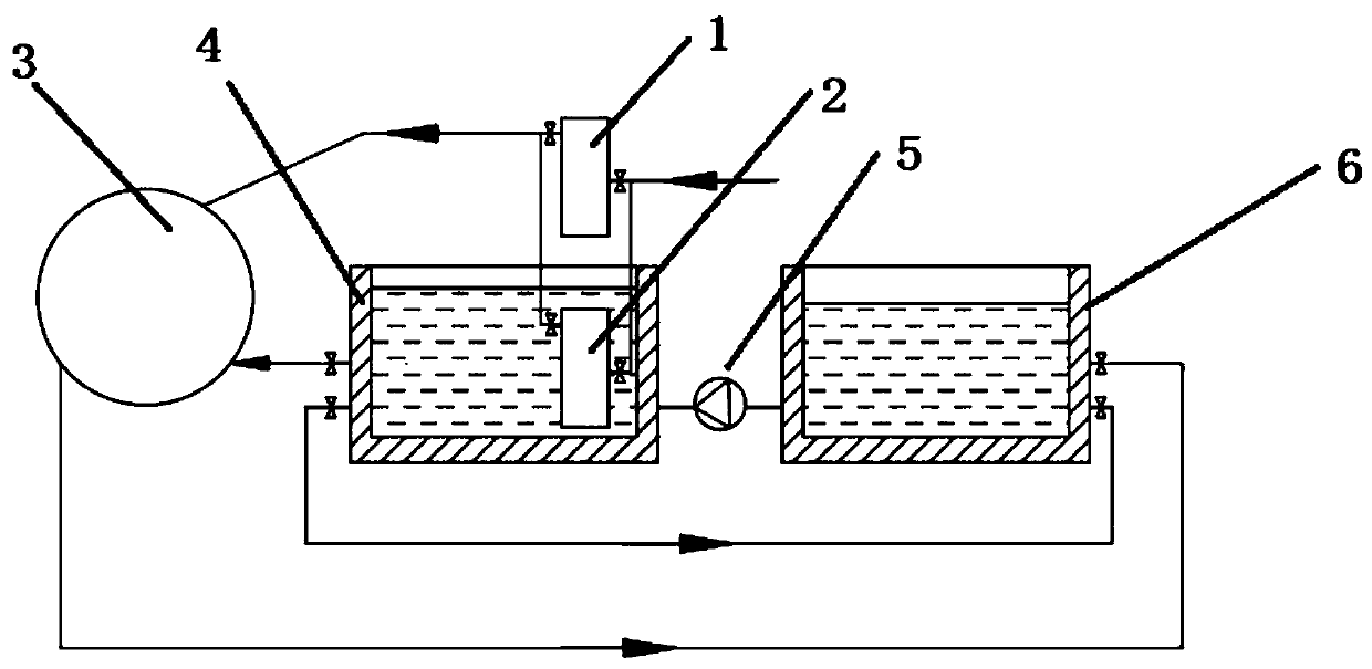
[0053] Specific embodiment 2, see image 3 , on the basis of the specific embodiment 1, it also includes an auxiliary vaporizer 1, the auxiliary vaporizer 1 and the vaporizer 2 are arranged in parallel, the inlets of the auxiliary vaporizer 1 and the vaporizer 2 are respectively connected to the liquid nitrogen delivery pipeline through a valve, the auxiliary vaporizer 1 and the vaporizer 2 The outlets of the outlets are respectively connected to nitrogen delivery pipelines through valves. Through the arrangement of the auxiliary vaporizer 1 , the problem of freezing of the water surface of the cooling water tank 4 during the heat absorption process of the vaporizer 2 is avoided. When the temperature in the cooling water tank 4 is lower than the set value (such as 10° C.) or the vaporizer 2 has been working for a certain period of time (such as 4 hours), the vaporization capacity of the vaporizer 2 decreases, and the vaporizer 2 does not transport liquid nitrogen, and the auxi...
PUM
 Abstract
Description
Claims
Application Information
 - R&D Engineer
- R&D Manager
- IP Professional
- Industry Leading Data Capabilities
- Powerful AI technology
- Patent DNA Extraction
Browse by: Latest US Patents, China's latest patents, Technical Efficacy Thesaurus, Application Domain, Technology Topic, Popular Technical Reports.
© 2024 PatSnap. All rights reserved.Legal|Privacy policy|Modern Slavery Act Transparency Statement|Sitemap|About US| Contact US: help@patsnap.com