
Anti-falling cement shovel plate for bricklayer on construction site

A construction site, anti-falling technology, applied in the processing of building materials, construction, building structure, etc., can solve problems such as inconvenience, material loss, time-consuming and laborious, and achieve convenient tool storage, good use effect, and convenient use. Effect

Inactive Publication Date: 2020-03-27
钱厚文
View PDF0 Cites 1 Cited by
  • Summary
  • Abstract
  • Description
  • Claims
  • Application Information

AI Technical Summary

Problems solved by technology

[0002] Cement is more commonly used on construction sites, because when building walls, cement slurry is required between bricks, and cement is also required on the wall surface. When workers plaster walls, they usually use cement. The cement shovel scoops the cement slurry from the container, and then uses the trowel to divide the cement slurry on the cement shovel and smooth it on the wall. The disadvantage of the general cement shovel is that the bricklayer puts the cement After the slurry is shoveled on the cement shovel, the cement slurry tends to flow down and fall easily, resulting in material loss. In this way, bricklayers need to use the trowel to continuously mix the cement slurry on the cement slab, which is time-consuming and laborious, and not convenient enough

Method used


Image

  • Anti-falling cement shovel plate for bricklayer on construction site
  • Anti-falling cement shovel plate for bricklayer on construction site
  • Anti-falling cement shovel plate for bricklayer on construction site

Examples


Embodiment Construction

[0016] The following will clearly and completely describe the technical solutions in the embodiments of the present invention with reference to the accompanying drawings in the embodiments of the present invention. Obviously, the described embodiments are only some, not all, embodiments of the present invention. Based on the embodiments of the present invention, all other embodiments obtained by persons of ordinary skill in the art without making creative efforts belong to the protection scope of the present invention.

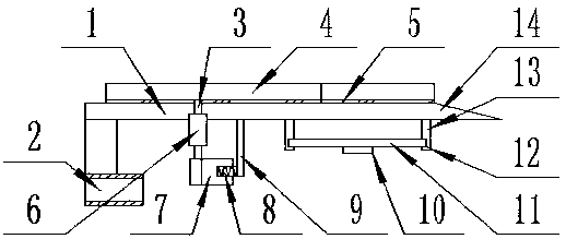
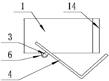
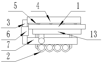
[0017] see Figure 1-3 , the present invention provides a technical solution: an anti-falling cement shovel for construction site bricklayers, including a flat plate 1, a shaft cylinder 6 is vertically fixed on the left side of the front end of the flat plate 1, and the inside of the shaft cylinder 6 is vertically fixed. A rotating shaft 3 is inserted, and an L-shaped baffle 4 is arranged horizontally on the upper surface of the flat plate 1, and the left side...


PUM


Abstract

The invention discloses an anti-falling cement shovel plate for a bricklayer on a construction site. The anti-falling cement shovel plate comprises a flat plate, a shaft barrel is vertically and fixedly connected to the left side of the front end of the flat plate, and a rotating shaft is vertically inserted into the shaft barrel; an L-shaped baffle is horizontally arranged on the upper end face of the flat plate, the left side of the L-shaped baffle is fixedly connected with the upper end of the rotating shaft, a pull plate is fixedly connected to the lower end of the rotating shaft and is parallel to a right side plate of the L-shaped baffle, and a connecting rod is vertically and fixedly connected to the lower end face of the flat plate and located on the right side of the pull plate. According to the invention, fingerstalls are fixedly connected to the left side of the lower end face of the flat plate, so that fingers of a user can conveniently penetrate through a holding device; then the cement paste is shoveled to the flat plate through the inclined shovel head at the right end of the flat plate; and then the pull plate located on the right side of the fingerstalls is shiftedleftwards with fingers, the pull plate drives the L-shaped baffle to rotate to the coinciding position of the front side edge and the right side edge of the flat plate through the connected rotatingshaft, the flat plate inclines forwards, and therefore, the L-shaped baffle blocks cement paste; the plate provided by the invention is simple in structure, convenient to use and good in using effect.

Description

technical field [0001] The invention relates to the technical field of construction, in particular to an anti-falling cement shovel for bricklayers on construction sites. Background technique [0002] Cement is more commonly used on construction sites, because when building walls, cement slurry is required between bricks, and cement is also required on the wall surface. When workers plaster walls, they usually use cement. The cement shovel scoops the cement slurry from the container, and then uses the trowel to divide the cement slurry on the cement shovel and smooth it on the wall. The disadvantage of the general cement shovel is that the bricklayer puts the cement After the slurry is shoveled on the cement shovel, the cement slurry tends to flow down and fall easily, resulting in material loss. In this way, bricklayers need to use the trowel to continuously mix the cement slurry on the cement slab, which is time-consuming and laborious, and not convenient enough. Content...

Claims


Application Information

Patent Timeline
IPC IPC(8): E04G21/20
CPCE04G21/201
Inventor 钱厚文
Owner 钱厚文
Learn More