
Cutoff mechanism for carbon fiber tape feeder

A cutting mechanism, carbon fiber technology, applied in the cutting of textile materials, textiles and papermaking, etc., can solve the problems of insufficient air supply and continuous cutting of carbon fiber material, and achieve the effect of high efficiency

Inactive Publication Date: 2020-03-27
浙江虹腾新材料有限公司
View PDF8 Cites 0 Cited by
  • Summary
  • Abstract
  • Description
  • Claims
  • Application Information

AI Technical Summary

Problems solved by technology

At present, carbon fiber strips are generally cut by cylinders during processing, and during long-term use of the cylinders, the carbon fiber strips will continue to be cut due to the offset of the induction line or insufficient air supply.

Method used


Image

  • Cutoff mechanism for carbon fiber tape feeder
  • Cutoff mechanism for carbon fiber tape feeder
  • Cutoff mechanism for carbon fiber tape feeder

Examples


Embodiment Construction

[0020] In order to make the technical means, creative features, goals and effects achieved by the present invention easy to understand, the present invention will be further elaborated below in conjunction with illustrations and specific embodiments.

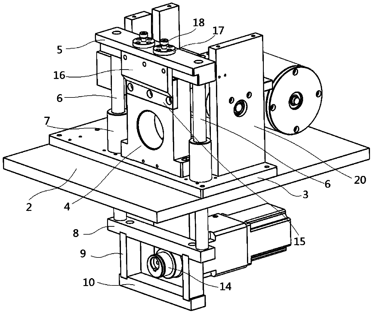
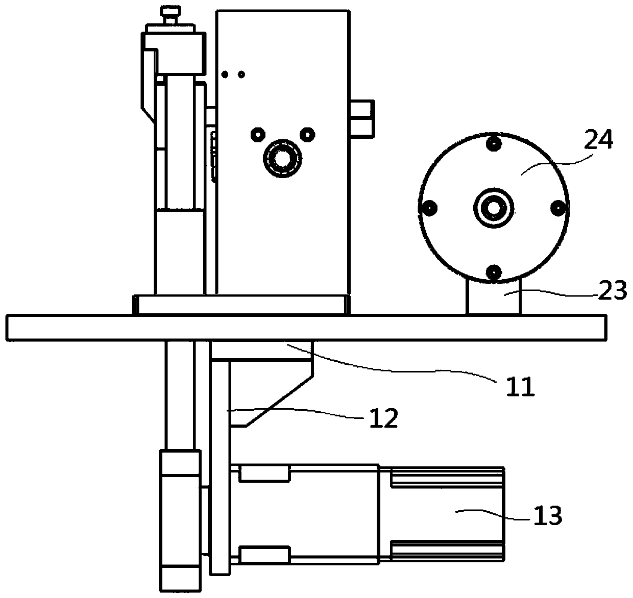
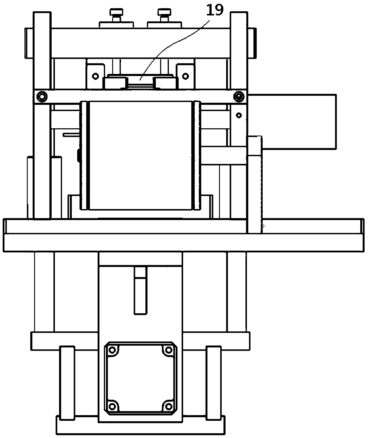
[0021] Such as Figure 1 to Figure 4 As shown, a cutting mechanism for carbon fiber strips proposed by the present invention includes a chassis and a base plate 2 fixed on the chassis; a cutter base plate 3 is fixed on the base plate 2, and a fixed Seat 4, the upper side of the fixed seat 4 is provided with an upper knife seat 5, and the lower side of the upper knife seat 5 is fixed with two guide posts 6, and the two guide posts 6 are located on both sides of the fixed seat 4; Two guide posts 6 extend downward into the cabinet 1, and two guide sleeves 7 are fixed on the cutter bottom plate 3, and the two guide sleeves 7 are sleeved on the outside of the guide post 6; the two guide posts The lower end of 6 is fixed with a beari...


PUM


Abstract

The invention discloses a cutting mechanism for a carbon fiber tape feeder, which comprises a case and a bottom plate fixed on the case; a cutter bottom plate is fixed on the base plate, a fixed seatis fixed on the cutter base plate, an upper cutter head is arranged on an upper side of the fixed seat, two guide pillars are fixed on a lower side of the upper cutter head, and the two guide pillarsare positioned on two sides of the fixed seat; the two guide pillars extend downwards into the case, two guide sleeves are fixed on the cutter bottom plate, and the outsides of the guide pillars are sleeved with the two guide sleeves; a bearing fixing upper plate is fixed at lower side ends of the two guide pillars, two bearing fixing side plates are fixed at the lower side of the bearing fixing upper plate, a bearing fixing lower plate is fixed at the lower side ends of the two bearing fixing side plates, and a rectangular frame is formed between the two bearing fixing side plates and the bearing fixing lower plate.

Description

technical field [0001] The invention relates to the field of mechanical processing, in particular to a cutting mechanism for carbon fiber strips. Background technique [0002] Carbon fiber is a special fiber composed of carbon elements. It has the characteristics of high temperature resistance, friction resistance, electrical conductivity, heat conduction and corrosion resistance. It is fibrous and soft, and can be processed into various fabrics. Because its graphite microcrystalline structure is preferentially oriented along the fiber axis, it has a high density along the fiber axis. strength and modulus. Carbon fiber has a low density, so its specific strength and specific modulus are high. The main purpose of carbon fiber is to compound with resin, metal, ceramics and carbon as a reinforcing material to manufacture advanced composite materials. Carbon fiber reinforced epoxy resin composites have the highest specific strength and specific modulus among existing engineer...

Claims


Application Information

Patent Timeline
IPC IPC(8): D06H7/02
CPCD06H7/02
Inventor 鲍泉华
Owner 浙江虹腾新材料有限公司
Learn More