
Laser spot welder and range hood production process applying laser spot welder

A technology of laser spot welding and lasers, which is applied in laser welding equipment, welding/welding/cutting items, welding media, etc., and can solve problems such as non-adherence, affecting welding efficiency, and inability to weld

Active Publication Date: 2020-03-27
绍兴依利奥厨具有限公司
View PDF8 Cites 2 Cited by
  • Summary
  • Abstract
  • Description
  • Claims
  • Application Information

AI Technical Summary

Problems solved by technology

[0004] The above-mentioned technical solution has the following defects: during the welding process, the jitter generated by the movement of the longitudinal sliding frame and the working platform may cause a gap between the metal frame and the metal plate, failing to fit, when the laser If the irradiated position is not close to each other, it will lead to failure to weld; and foreign objects may not be able to press against the metal frame and metal plate, which will also cause the two to be not close to each other and cannot be welded, which will greatly affect the welding efficiency

Method used


Image

  • Laser spot welder and range hood production process applying laser spot welder
  • Laser spot welder and range hood production process applying laser spot welder
  • Laser spot welder and range hood production process applying laser spot welder

Examples


Embodiment 1

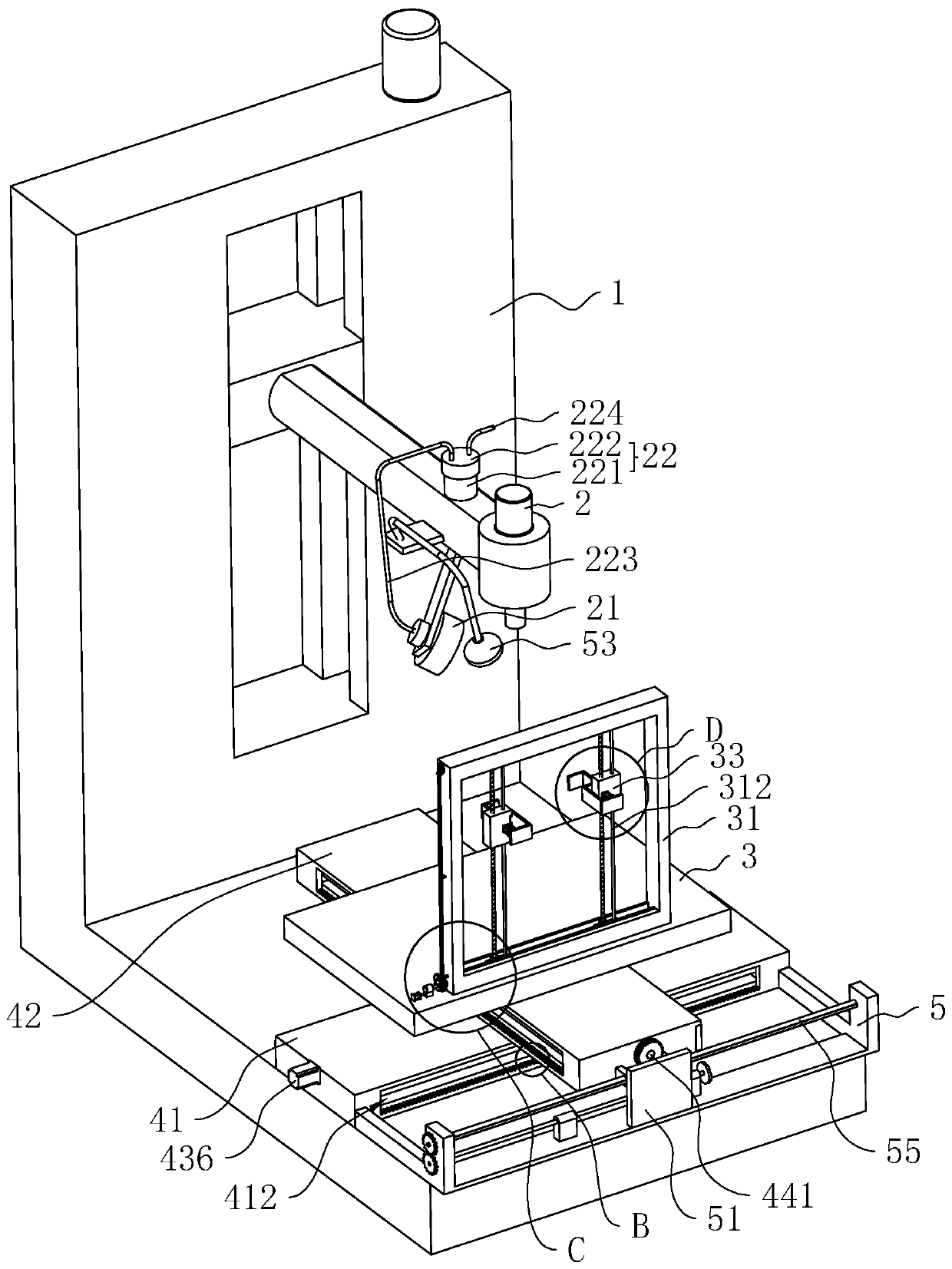
[0079] refer to figure 2 , a kind of laser spot welding machine, comprises frame 1, is provided with laser device 2, observation mechanism, moving mechanism on frame 1, is provided with workbench 3 on the moving mechanism, and laser device 2 is used for welding weldment, and observation mechanism provides staff Check the welding position, the moving mechanism drives the workbench 3 to move to realize the welding of the laser 2 to the weldment, and the workbench 3 is provided with a clamping mechanism for clamping the weldment.

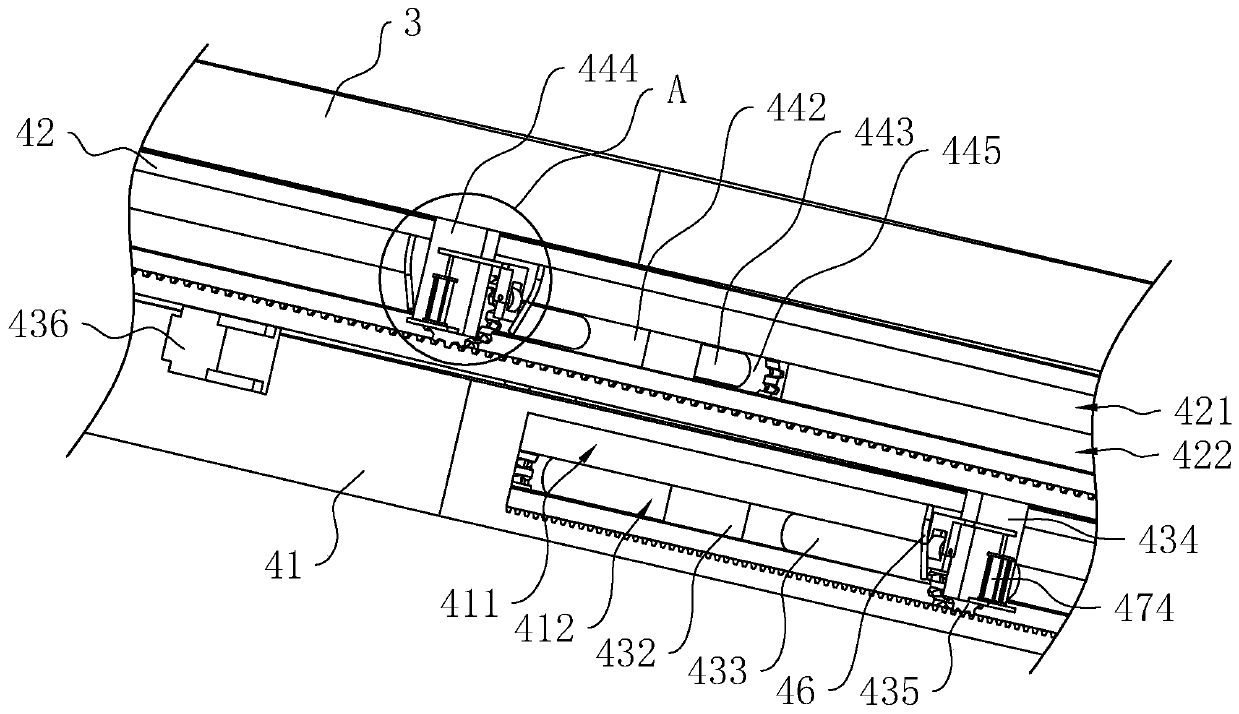
[0080] refer to figure 2 with image 3 , the moving mechanism includes a horizontal adjustment frame 41 and a longitudinal adjustment frame 42, the horizontal adjustment frame 41 is fixedly arranged on the frame 1, the longitudinal adjustment frame 42 is slidingly arranged on the horizontal adjustment frame 41, and the horizontal adjustment frame 41 is provided with a The fourth drive assembly connected to the adjustment frame 42 , the worktable 3 ...

Embodiment 2

[0112] A production process of range hood, comprising the following process steps:

[0113] S1: Cut stainless steel raw materials with a cutting machine to obtain raw material composite plates;

[0114] S2: Bending and stamping the raw material combination board with a punching machine to obtain the finished combination board;

[0115] S3: Pre-treat the welding surface of the composite board first, then assemble the finished composite board, and weld the composite board with the laser spot welding machine in Embodiment 1, and form a primary weld seam at the welding place of the composite board to obtain a semi-finished range hood casing;

[0116] The preprocessing steps are as follows:

[0117] Step a: Clean the welding surface of the finished composite board with a hot lye solution with a pH of 8-9 and a temperature of 50-60°C, then rinse with deionized water, and dry for use;

[0118] Step b: Spray the welding strengthening agent on the welding surface with a high-pressure...

Embodiment 1

[0125] The difference between Examples 18-22 and Example 1 is that each component in the active agent is calculated in the following table by weight percentage.

[0126]


PUM


Abstract

The invention relates to a laser spot welder and a range hood production process applying the laser spot welder, and relates to the technical field of welding equipment. The laser spot welder comprises a machine frame; a laser, an observation mechanism and a moving mechanism are arranged on the machine frame; a worktable is arranged on the moving mechanism; a clamping mechanism is arranged on theworktable; the clamping mechanism comprises a fixed frame mounted on the worktable; two moving seats are arranged on the fixed frame in a sliding manner; a first clamping block is mounted on the moving seat; a second clamping block is mounted on the moving seat in the sliding manner; space used for clamping a welding piece is formed between the opposite sides of the first clamping block and the second clamping block; a first driving component is arranged on the fixed frame; and a second driving component which is connected with the moving seat is arranged on the fixed frame. According to the laser spot welder and the range hood production process applying the laser spot welder, the welding piece is clamped through the first clamping block and the second clamping block so as to realize thefixation of the welding piece; the probability of a welding seam is reduced; the probability of welding missing when the laser performs welding is reduced; the welding quality is improved; and the defective rate is reduced.

Description

technical field [0001] The invention relates to the technical field of welding equipment, in particular to a laser spot welding machine and a production process of a range hood using the laser spot welding machine. Background technique [0002] Laser spot welding is the use of high-energy laser pulses to locally heat materials in a small area. The energy of laser radiation diffuses into the interior of the material through heat conduction, and the material is melted to form a specific molten pool, thereby welding the same or different materials. together. [0003] Existing laser spot welding machines such as figure 1 As shown, the frame 1 is included, the frame 1 is provided with a horizontal adjustment frame 41, the horizontal adjustment frame 41 is slid to be provided with a longitudinal adjustment frame 42, and the longitudinal adjustment frame 42 is slid to be provided with a workbench 3; the horizontal adjustment frame 41 A lead screw motor is provided inside, and the...

Claims


Application Information

Patent Timeline
Patent Type & Authority Applications(China)
IPC IPC(8): B23K26/22B23K37/04B23K37/047B23K26/70B23K26/60B23P15/00B23K31/12B23K35/30B23K35/36B23K26/142B23K103/04
CPCB23K26/22B23K37/0435B23K37/047B23K26/702B23K26/60B23P15/00B23K31/12B23K35/3053B23K35/3613B23K26/142B23K2103/05
Inventor 罗丹丹黄超年蒋英易智能林红
Owner 绍兴依利奥厨具有限公司
Learn More