Arrangement and method for disturbance correction for imaging flow measuring processes

A flow measurement and imaging technology, which is applied in the direction of measuring devices, liquid/fluid solid measurement, flow measurement/mass flow, etc., can solve problems such as multiple reflections, impossible instantaneous correction of field of view, and inability to form boundary surfaces, etc., to achieve a simple structure Effect

Active Publication Date: 2020-03-24
DRESDEN UNIVERSITY OF TECHNOLOGY
View PDF6 Cites 2 Cited by
  • Summary
  • Abstract
  • Description
  • Claims
  • Application Information

AI Technical Summary

Problems solved by technology

Scattering of light on tissue results in multiple reflections, which prevent any defined boundary surfaces from forming
Disadvantageously, the correction of optical distortions on the retina can thus only be perfo...

Method used


Image

  • Arrangement and method for disturbance correction for imaging flow measuring processes
  • Arrangement and method for disturbance correction for imaging flow measuring processes
  • Arrangement and method for disturbance correction for imaging flow measuring processes

Examples


Embodiment Construction

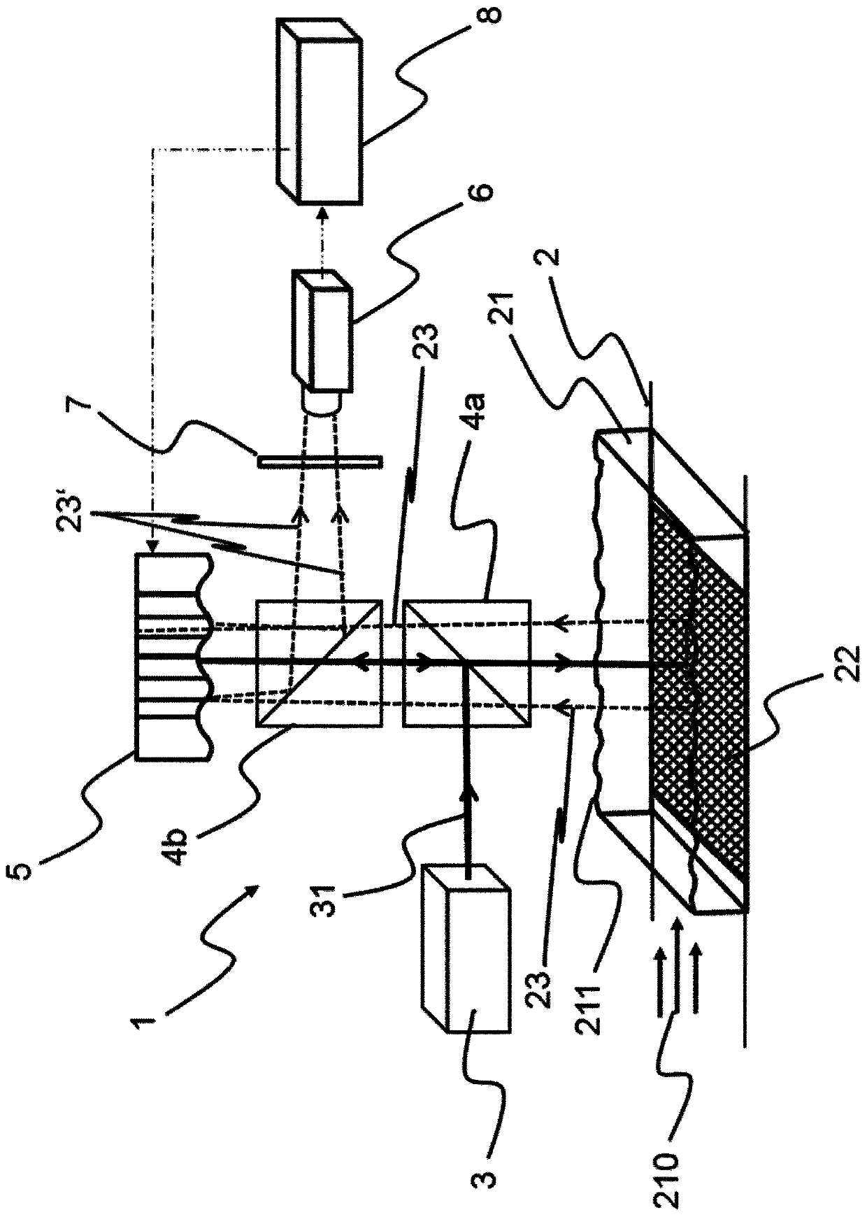
[0109] figure 1 An exemplary embodiment of a wavefront-less sensor device 1 for correcting optical disturbances by undulating boundary surfaces 211 in imaging flow measurement methods is shown. A fluid 21 flows through the flow channel 2 in a flow direction 210 , wherein the fluid 21 has an open boundary surface 211 facing the environment. Scattering at the open boundary surface 211 thus causes fluctuating optical disturbances. For measurement by means of imaging flow measurement methods, the fluid 21 contains scattering particles (not shown). A static pattern 22 is provided at the bottom of the flow channel 2 .

[0110] The illumination source 3 emits illumination light 31 which is guided via the beam splitter 4a and the further beam splitter 4b to the surface light modulator 5 and thus reflected in the direction of the flow channel 2 in order to illuminate through the boundary surface 211 Flow fluid 21 and pattern 22 . In the exemplary embodiment, the measurement field r...


PUM


Abstract

A generally time-varying boundary surface between multiple flowing fluids with different refractive indices, for example the boundary surface between water and air with a free water surface, represents an optical disturbance. Optical flow measuring processes that take place through the boundary surface are influenced by this disturbance, which leads to significant measurement deviations or even completely prevents measurement. The invention contributes to solving this technical measurement problem by proposing arrangements (1, 1a, 1') and processes for the instantaneous, hardware-based correction of the optical disturbances caused by a fluctuating boundary surface (211). For this purpose, a wavefront modulator (5) is introduced into the beam of the optical measuring process and, by means of a feedback control, actively compensates for the optical disturbance that is caused. The invention makes it possible to perform optical flow measurements through a fluctuating boundary surface. It is at the same time not restricted to a single flow measuring process but can be implemented in all known imaging processes. The invention can be used in a large number of technical applications. To bementioned by way of example are: liquid-air boundary surfaces, for example in water channels with an open surface; film flows, for example in chemical process engineering for cooling, cleaning or distillation; liquid jets with the surface fluctuating on all sides; measurements in levitated drops or drops adhering on an opaque underlying surface or gas bubbles occurring in liquids. The invention is also suitable for the correction of disturbances due to temperature gradients in combustion processes, pressure gradients, for example in the case of pressure surges, or concentration gradients, forexample in the case of electrolytic processes.

Description

technical field [0001] The present invention relates to an arrangement and a method for interference correction of a flow measurement method, in particular an arrangement and a method for interference correction of an imaging flow measurement method. Background technique [0002] Many treatments in chemical engineering involve fluids with different refractive indices separated by boundary surfaces. This boundary surface typically changes with time. The resulting refractive index fluctuations represent time-varying fluctuating optical disturbances. This can greatly reduce the performance of the optical measurement method or make the measurement impossible at all. For example, in an open surface in a pool where waves may form, light rays are randomly refracted at the water-air boundary surface, and using this boundary surface to measure flow velocity in water is heavily affected by disturbances. Fluctuating boundary surfaces are therefore a major challenge for flow measurem...

Claims


Application Information

Patent Timeline
IPC IPC(8): G02B26/06G01N21/03G02B27/00
CPCG02B26/06G02B27/0068G01F1/661
Inventor 拉尔斯·比特纳于尔根·察尔斯克马丁·泰希内克塔里奥斯·库库拉基斯
Owner DRESDEN UNIVERSITY OF TECHNOLOGY
Why Eureka
Try Eureka