Deep hole blasting charge structure
A technology of deep hole blasting and charging, which is applied in the field of blasting. It can solve the problems of inconvenient shipping and processing, increase the amount of explosives, and increase operating costs, etc., and achieve the effects of saving production costs, good blasting and cutting effects, and reducing the rate of large pieces.
- Summary
- Abstract
- Description
- Claims
- Application Information
AI Technical Summary
Problems solved by technology
Method used
Image
Examples
specific Embodiment 1
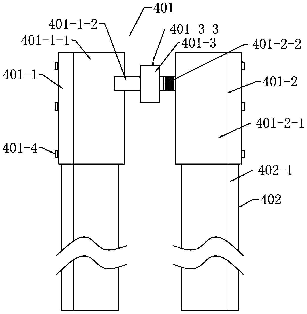
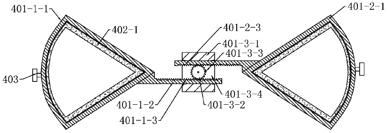
[0025] Specific Example 1: See Figure 1 to Figure 4 , in the embodiment of the present invention, a kind of deep hole blasting charge structure, comprises blast hole, and the aperture of described blast hole has packing layer 1, and the depth of packing layer 1 of described blast hole aperture is 25 times of blast hole diameter , the middle of the packing layer 1 is filled with broken drug packs 101 . Along the direction of the depth of the blast hole from top to bottom, it also includes a blasting bag 2, a first charge layer 3, a second charge layer 6 and a hole bottom energy-gathering ring 7, and the blasting bag 2 is filled with There is water or gas.
[0026] The first charge layer 3 includes an adjustable energy-concentrating tube combination device 4 and explosives 5. The adjustable energy-concentrating tube combination device 4 includes two adjustment assemblies 401 and two groups of energy-concentrating tube groups 402 with the same structure. The group 402 is arran...
specific Embodiment 2
[0032] Specific embodiment 2: on the basis of embodiment 1, refer to Figure 5The depth of the packing layer 1 of the blast hole opening is 30 times the diameter of the blast hole, and the adjustable energy-collecting tube group 402 and the device 4 include three adjustment assemblies 401 and two groups of energy-collecting tube groups 402 with the same structure. The energy collecting tube group 402 is composed of three energy collecting tubes 402 - 1 connected together, and the energy collecting tubes 402 - 1 can be connected in series through the adjustment assembly 401 . The wall thickness of the side wall of the energy collecting tube 402-1 is 2.3 mm, and the wall thickness of the arc edge of the energy collecting tube 402-1 is 1.5 mm. The angle formed between the two sidewalls of the energy collecting tube 402-1 is the energy collecting angle α, and the angle of the energy collecting angle α is 90°.
specific Embodiment 3
[0033] Specific Example 3: See Image 6 The difference between this embodiment and Embodiment 1 is that the fastener is a screw 401-3, and the first adjustment belt 401-1-2 and the second adjustment belt 401-2-2 are respectively provided with several threaded holes 404, the first adjustment belt 401-1-2 and the second adjustment belt 401-2-2 are attached in parallel and are fixedly connected by screws 401-3. When assembling, only the first adjustment belt 401-1-2 After the position of the second adjustment belt 401-2-2 is placed at the set position, the first adjustment belt 401-1-2 and the second adjustment belt 401-2-2 are directly connected and fixed by the screw 401-3, and assembled Simple structure and convenient adjustment.
PUM
| Property | Measurement | Unit |
|---|---|---|
| Wall thickness | aaaaa | aaaaa |
Abstract
Description
Claims
Application Information
 - R&D
- Intellectual Property
- Life Sciences
- Materials
- Tech Scout
- Unparalleled Data Quality
- Higher Quality Content
- 60% Fewer Hallucinations
Browse by: Latest US Patents, China's latest patents, Technical Efficacy Thesaurus, Application Domain, Technology Topic, Popular Technical Reports.
© 2025 PatSnap. All rights reserved.Legal|Privacy policy|Modern Slavery Act Transparency Statement|Sitemap|About US| Contact US: help@patsnap.com


