
Thread end winding prevention transfer frame for garment processing plant

A technology for transfer racks and workshops, applied in the field of transfer racks, can solve the problems of easy involvement, small gap between rollers and mounting plates, fluff and dust falling, etc., so as to avoid difficult cleaning and improve transportation efficiency.

Active Publication Date: 2020-03-24
浙江圣麦斯针织有限公司
View PDF6 Cites 0 Cited by
  • Summary
  • Abstract
  • Description
  • Claims
  • Application Information

AI Technical Summary

Problems solved by technology

[0002] A large number of thread ends and cloth ends are produced during the garment production process, and these thread ends and cloth ends are cleaned up centrally, while the semi-finished products between the various stations in the factory building need to be transferred back and forth on the transfer frame, and the rollers under the transfer frame are running over The thread and cloth ends on the ground are easy to get involved in the rotating shaft of the roller. After a period of use, the thread and cloth ends will become more and more tightly entangled, and eventually the roller cannot rotate at all, and the gap between the roller and the mounting plate is very small. It is very difficult to clean thread and cloth ends, and many garment manufacturers directly repair them by replacing parts
[0003] There is also a large amount of fluff dust floating in the production workshop of the garment factory. When the semi-finished product is transported on the transfer rack, the fluff dust falls on the surface of the semi-finished product, which has a serious impact on the processing quality of the finished garment. For this reason, a garment processing plant is invented to prevent thread winding. Running rack

Method used


Image

  • Thread end winding prevention transfer frame for garment processing plant
  • Thread end winding prevention transfer frame for garment processing plant
  • Thread end winding prevention transfer frame for garment processing plant

Examples


Embodiment Construction

[0030] The following will clearly and completely describe the technical solutions in the embodiments of the present invention with reference to the accompanying drawings in the embodiments of the present invention. Obviously, the described embodiments are only some, not all, embodiments of the present invention. Based on the embodiments of the present invention, all other embodiments obtained by persons of ordinary skill in the art without making creative efforts belong to the protection scope of the present invention.

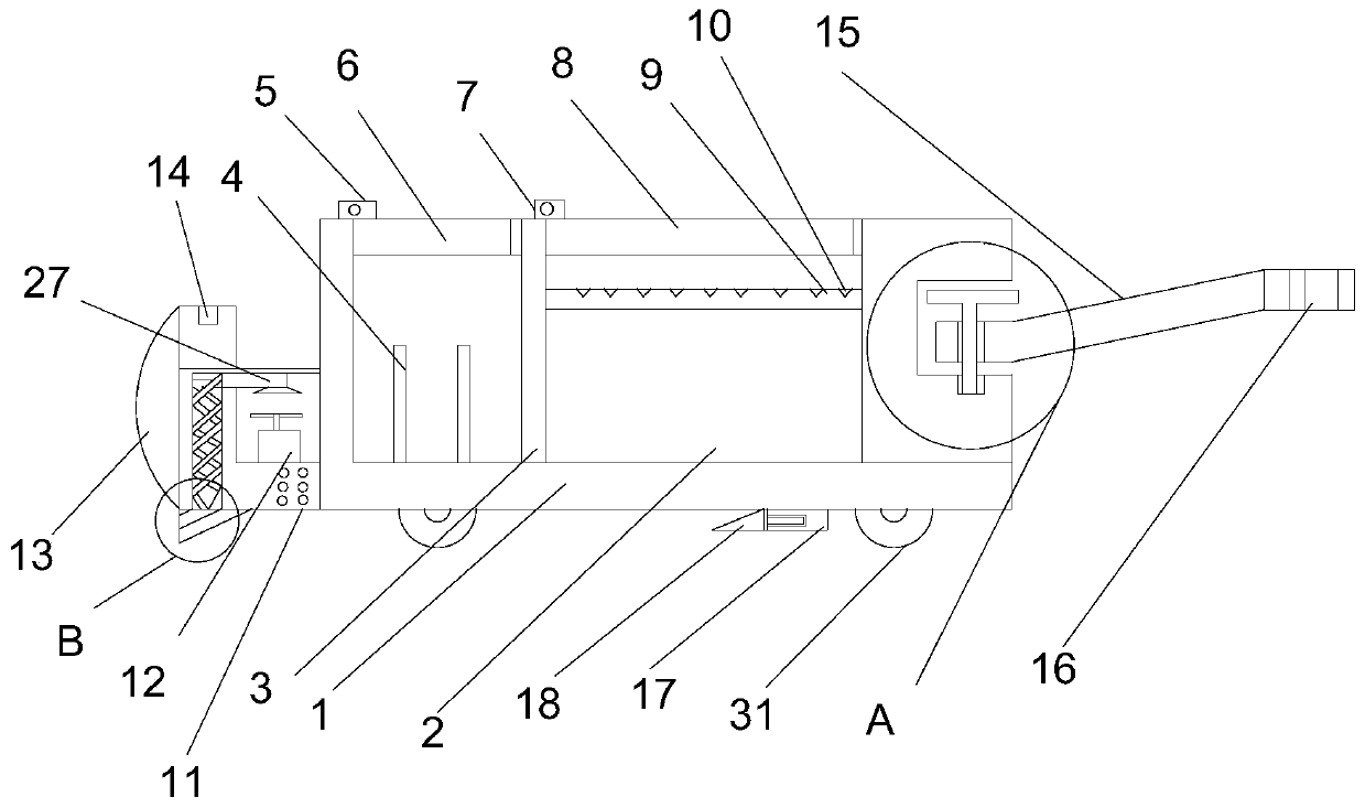
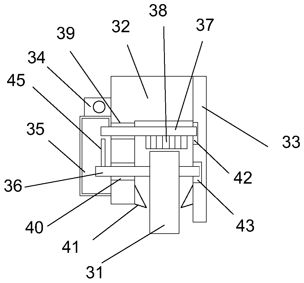
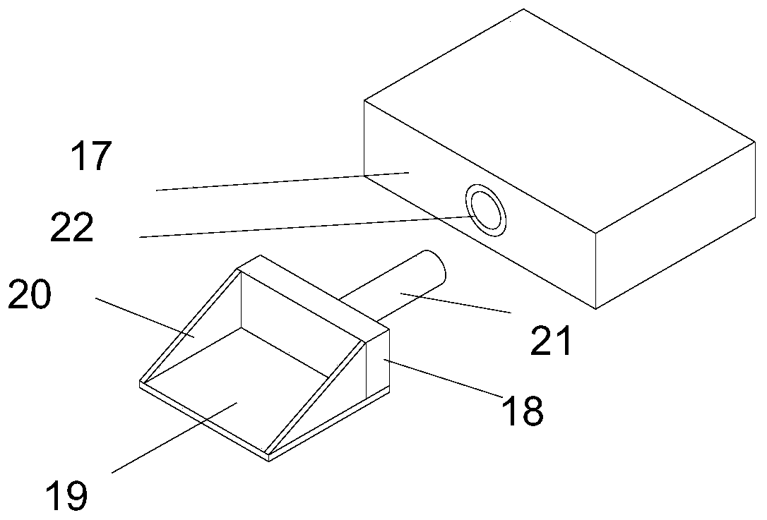
[0031] see Figure 1-8 , the present invention provides a technical solution: a transfer rack for preventing thread entanglement in a garment processing factory, including a main body 1, the main body 1 is a rectangular structure, and a storage tank 2 is opened on the upper wall of the main body 1, and the storage tank 2 is opened on the upper wall of the main body 1. The groove 2 is a rectangular groove, and the inside of the storage tank 2 is provided with a...


PUM


Abstract

The invention discloses a thread end winding prevention transfer frame for a garment processing plant, and relates to the technical field of textile equipment. The thread end winding prevention transfer frame for the garment processing plant includes a body, the body is of rectangular structure, a storage groove is formed in the upper wall surface of the body; the storage tank is a rectangular tank; a separation plate is arranged in the storage tank; the separation plate is a plate with a rectangular structure; the lower wall surface of the separation plate is fixedly connected to the bottom surface of the storage tank; the interior of the storage tank is separated into two parts by the separation plate. According to the invention, air is blown in from one side of the exhaust pipe throughthe blower; air entering the exhaust pipe enters the spiral pipes from the exhaust pipe; the ain moves in the rotating spiral pipe, the ain blown out from the triangular block does rotating acceleration motion, the rotating acceleration air is blown out from the interior of the inclined triangular block, thread residues and cloth residues on the ground of a road in front of wheels are blown away in advance, and the situation that the thread residues and the cloth residues wind the rotating frame is avoided.

Description

technical field [0001] The invention relates to the technical field of textile equipment, in particular to a transfer rack for preventing thread entanglement in garment processing workshops. Background technique [0002] A large number of thread ends and cloth ends are produced during the garment production process, and these thread ends and cloth ends are cleaned up in a centralized manner, while the semi-finished products between the various stations in the factory building need to be transferred back and forth on the transfer frame, and the rollers under the transfer frame are rolling over The thread and cloth ends on the ground are easy to get involved in the rotating shaft of the roller. After a period of use, the thread and cloth ends will become more and more tightly entangled, and eventually the roller cannot rotate at all, and the gap between the roller and the mounting plate is very small. It is very difficult to clean thread and cloth ends, and many garment manufa...

Claims


Application Information

Patent Timeline
IPC IPC(8): B62B3/00B62B5/00
CPCB62B3/005B62B5/00B62B2202/00
Inventor 王亮
Owner 浙江圣麦斯针织有限公司
Learn More