
Rubber wheel for trolley and production process thereof

A production process and rubber wheel technology, applied in the direction of wheels, wheel testing, wheels made of non-metallic materials, etc., can solve the problems of easy falling off, wheel hub damage, etc., and achieve the effect of not easy to break, not easy to damage, not easy to fall off

Pending Publication Date: 2020-03-24
嘉兴智悦橡塑股份有限公司
View PDF13 Cites 1 Cited by
  • Summary
  • Abstract
  • Description
  • Claims
  • Application Information

AI Technical Summary

Problems solved by technology

[0004] The present invention provides a rubber wheel for trolley and its production process, which solves the problem that the wheels of traditional trolleys are generally produced separately from the hub and the rubber outer ring, and then the rubber outer ring is formed on the outer hub of the hub to form the wheel. The hub and the rubber outer ring are separated, and the rubber outer ring is sleeved on the outer ring of the hub, which is easy to fall off, causing damage to the hub

Method used


Image

  • Rubber wheel for trolley and production process thereof
  • Rubber wheel for trolley and production process thereof
  • Rubber wheel for trolley and production process thereof

Examples


Embodiment 1

[0054] S1, first prepare the material of the rubber outer ring 20, mainly select raw rubber and vulcanizing agent, first bake the raw rubber at a temperature of 60°C to soften, then cut the rubber into small pieces, and then screen the vulcanizing agent.

[0055] S2, the materials are placed in the rubber mixing machine in the order of raw rubber, accelerator, high wear-resistant furnace carbon black, engine oil and vulcanizing agent (sulfur). The roller temperature of the rubber mixing machine is controlled at 40°C, and then the Stir to fully stir the materials so that the above ingredients can be evenly distributed in the raw rubber.

[0056] S3, put the material prepared in S2 into an automatic rubber vulcanizer, and vulcanize at a temperature of 145° C. for 15 minutes to convert plastic rubber into elastic rubber.

[0057] S4, press the elastic rubber material into the rubber outer ring 20 mold, cool down, open the mold, and take out the rubber outer ring 20 .

[0058] S5...

Embodiment 2

[0063] S1, first prepare the material of the rubber outer ring 20, mainly select raw rubber and vulcanizing agent, first bake the raw rubber at a temperature of 60°C to soften, then cut the rubber into small pieces, and then screen the vulcanizing agent.

[0064] S2, the materials are placed in the rubber mixing machine in the order of raw rubber, accelerator, high wear-resistant furnace carbon black, engine oil and vulcanizing agent (sulfur). The roller temperature of the rubber mixing machine is controlled at 40°C, and then the Stir to fully stir the materials so that the above ingredients can be evenly distributed in the raw rubber.

[0065] S3, put the material prepared in S2 into an automatic rubber vulcanizer, and vulcanize at a temperature of 155° C. for 20 minutes to convert plastic rubber into elastic rubber.

[0066] S4, press the elastic rubber material into the rubber outer ring 20 mold, cool down, open the mold, and take out the rubber outer ring 20 .

[0067] S5...


PUM


Abstract

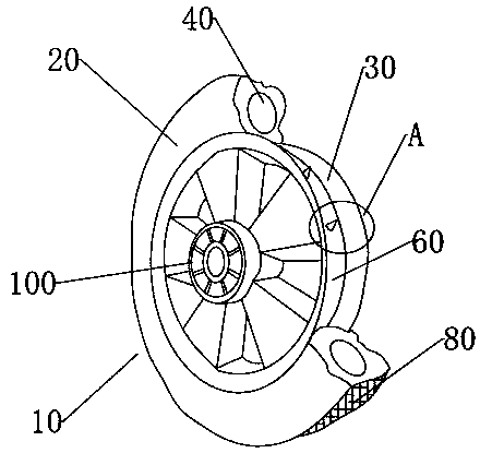
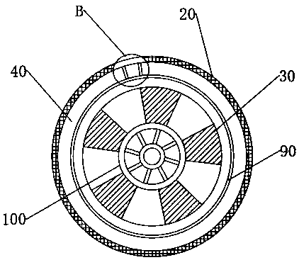
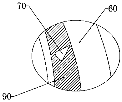
The invention provides a rubber wheel for a trolley and a production process of the rubber wheel. The rubber wheel comprises a rubber wheel body, wherein the rubber wheel body comprises a rubber outerring and a hub; the rubber outer ring wraps the outer side of the hub. The inner part of the rubber outer ring is hollow and annular; an elastic rod is arranged in the hollow cavity; a groove is formed in the end face of the outer circle of the hub. Antiskid spikes are arranged in the grooves; the anti-skid spikes are in contact with the rubber outer ring; the face, making contact with the rubberouter ring, of the groove is coated with a bonding layer. The problems that a hub and a rubber outer ring of a wheel of a traditional trolley are generally produced separately, then the produced hubis sleeved with the rubber outer ring to form the wheel, the hub and the rubber outer ring of the wheel are separated, the rubber outer ring is connected to the outer ring of the hub in a sleeving mode and is prone to falling off, and consequently the hub is damaged are solved.

Description

technical field [0001] The invention relates to the field of rubber wheels for trolleys, in particular to a rubber wheel for trolleys and a production process thereof. Background technique [0002] The trolley is a transport vehicle that is pushed and pulled by manpower. It is the ancestor of all vehicles. Although the material handling technology of the trolley continues to develop, the trolley is still used as an indispensable transportation tool; the trolley is widely used in production and life because It is cheap, easy to maintain, easy to operate, and light in weight. It can work in places where motor vehicles are inconvenient, and it is very convenient for short-distance handling of lighter items. The wheels of the trolley generally use solid wheels or pneumatic wheels; and now The wheels of some trolleys are generally produced separately from the hub and the rubber outer ring, and then the outer rubber ring is formed on the outer hub of the produced hub to form a whe...

Claims


Application Information

Patent Timeline
Patent Type & Authority Applications(China)
IPC IPC(8): B60B5/02B29D99/00G01M17/013
CPCB60B5/02B29D99/0032G01M17/013
Inventor 邵明峰
Owner 嘉兴智悦橡塑股份有限公司
Learn More