
Sedimentation furnace tube

A technology of deposition furnace and deposition process, which is applied in the direction of gaseous chemical plating, metal material coating process, coating, etc., to achieve the effects of flattening film thickness, increasing deposition rate, and improving yield

Pending Publication Date: 2020-03-20
CHANGXIN MEMORY TECH INC
View PDF0 Cites 3 Cited by
  • Summary
  • Abstract
  • Description
  • Claims
  • Application Information

AI Technical Summary

Problems solved by technology

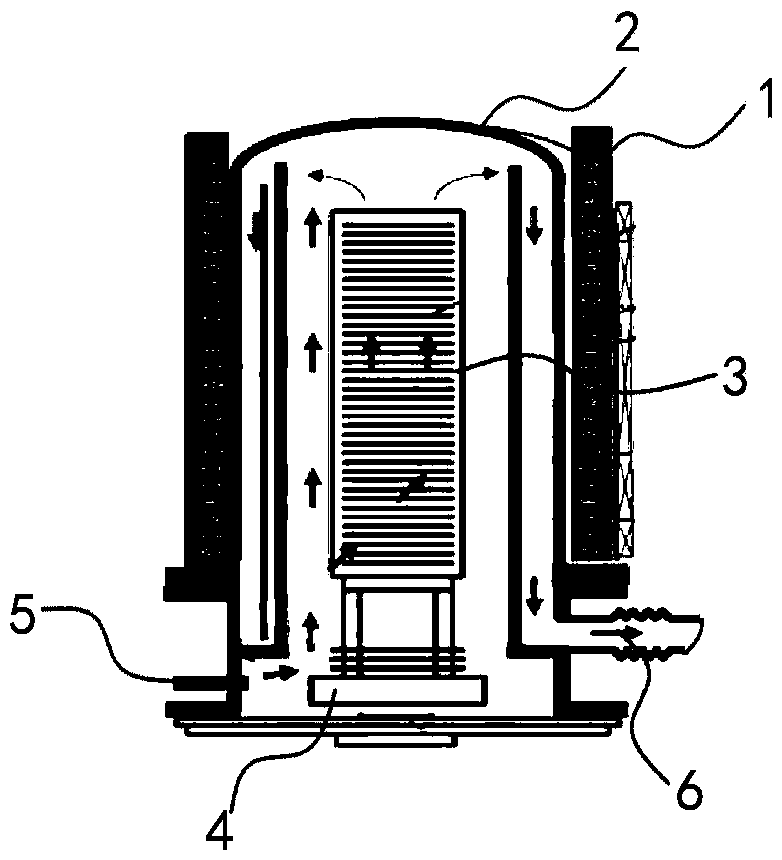
How to improve the structure of the existing deposition furnace tube to improve the uniformity of the deposition film thickness of the existing deposition furnace tube, accurately control the thickness of the side wall insulating layer, and help to achieve the thickness of the side wall insulating layer of the chip product Planarization has become a technical difficulty to be solved urgently in the thin film deposition process

Method used


Image

  • Sedimentation furnace tube
  • Sedimentation furnace tube
  • Sedimentation furnace tube

Examples


Embodiment Construction

[0021] Example embodiments will now be described more fully with reference to the accompanying drawings. Example embodiments may, however, be embodied in many forms and should not be construed as limited to the embodiments set forth herein; rather, these embodiments are provided so that this disclosure will be thorough and complete, and will fully convey the concept of example embodiments to those skilled in the art. In the drawings, the thicknesses of regions and layers may be exaggerated for clarity. The same reference numerals in the drawings denote the same or similar structures, and thus their detailed descriptions will be omitted.

[0022] Furthermore, the described features, structures, or characteristics may be combined in any suitable manner in one or more embodiments. In the following description, numerous specific details are provided in order to give a thorough understanding of embodiments of the invention. However, one skilled in the art will appreciate that th...


PUM

PropertyMeasurementUnit
thicknessaaaaaaaaaa

Abstract

The invention provides a sedimentation furnace tube which comprises a reaction cavity, a heater, a cassette, a base and an auxiliary heating part. One end of the reaction cavity is closed, and the other end of the reaction cavity is provided with an opening. The heater is arranged on the periphery of the reaction cavity. The cassette is located in the reaction cavity and used for bearing multiplebatches of wafers. The base supports the cassette and can drive the cassette to move into the reaction cavity and close the opening or drive the cassette to move out of the reaction cavity. The auxiliary heating part is arranged at one end of the reaction cavity and located above the cassette, and the auxiliary heating part heats the middles of the wafers on the top of the cassette when the heaterperforms heating.

Description

technical field [0001] The invention relates to the field of semiconductor manufacturing, in particular to a furnace tube for depositing thin films on wafers. Background technique [0002] In the semiconductor manufacturing process, various thin films need to be deposited on the wafer. Among various thin film deposition methods, Chemical Vapor Deposition (CVD, Chemical Vapor Deposition) is a commonly used method and has been widely used in various thin film deposition processes. Chemical vapor deposition is to transport the reaction gas to the deposition furnace tube, so that it can chemically react with the wafer in the furnace tube under certain conditions, so as to deposit a thin film on the surface of the wafer. [0003] For example, in the structure of DRAM (Dynamic Random Access Memory), a side wall insulating layer must be formed on the side wall, and the side wall insulating layer can isolate the plug conductive layer (doped polysilicon) in DRAM applications. And t...

Claims


Application Information

Patent Timeline
Patent Type & Authority Applications(China)
IPC IPC(8): C23C16/46C23C16/458C23C16/34
CPCC23C16/46C23C16/4581C23C16/345
Inventor 不公告发明人
Owner CHANGXIN MEMORY TECH INC
Learn More