A cable winding device

A technology of winding device and cable, applied in transportation and packaging, thin material handling, transportation of filamentous materials, etc., can solve the problems of high use cost and post-maintenance cost, complicated and cumbersome operation, and low winding efficiency. The effect of reducing production and maintenance costs, simplifying device structure, and improving convenience

Active Publication Date: 2021-09-21
JINAN SHENGTONG POWER CABLE
View PDF9 Cites 0 Cited by
  • Summary
  • Abstract
  • Description
  • Claims
  • Application Information

AI Technical Summary

Problems solved by technology

[0003] In the patent application publication number CN 108002115 A, a uniform winding power cable winding device is disclosed, including a base, a support beam, a feed slider, a screw rod, a screw rod, a moving slider, a guide ring, and a touch rod , reversing switch and winding roller, the two feed sliders are respectively sleeved on the outer circumferences of both sides of the screw rod through threaded connection, and the bottom ends of the two feed sliders are fixedly provided with support rods, The inner wall of the bottom end of the two support rods is fixedly equipped with a reversing switch, the moving slider is sleeved on the screw rod through a threaded connection, the bottom end of the moving slider is fixedly hung with a guide ring, and the outer side of the upper part of the moving slider A touch bar is symmetrically fixed on the wall, and the take-up roller is erected above the middle part of the base through the lifting mechanism; this invention can make the cable evenly wound around a specific area on the take-up roller, but its existence is as follows Disadvantages: When the application is rewinding the cable, two motors need to be used to realize the rotation of the screw and the rewinding roller. It is also necessary to continuously adjust the cable feed speed with the change of the diameter of the winding roller, the operation is complex and cumbersome, and the winding efficiency is low. At the same time, with the continuous winding of the cable, the length of the cable winding cannot meet the actual winding of the winding wheel. Therefore, the outer cable gap is larger than the inner cable gap. With the continuous winding of the cable, the coiled material will appear hollow and uneven, which will easily affect the overall aesthetics of the coiled material.

Method used


Image

  • A cable winding device
  • A cable winding device

Examples


Embodiment Construction

[0023] The following will clearly and completely describe the technical solutions in the embodiments of the present invention with reference to the accompanying drawings in the embodiments of the present invention. Obviously, the described embodiments are only some, not all, embodiments of the present invention. Based on the embodiments of the present invention, all other embodiments obtained by persons of ordinary skill in the art without making creative efforts belong to the protection scope of the present invention.

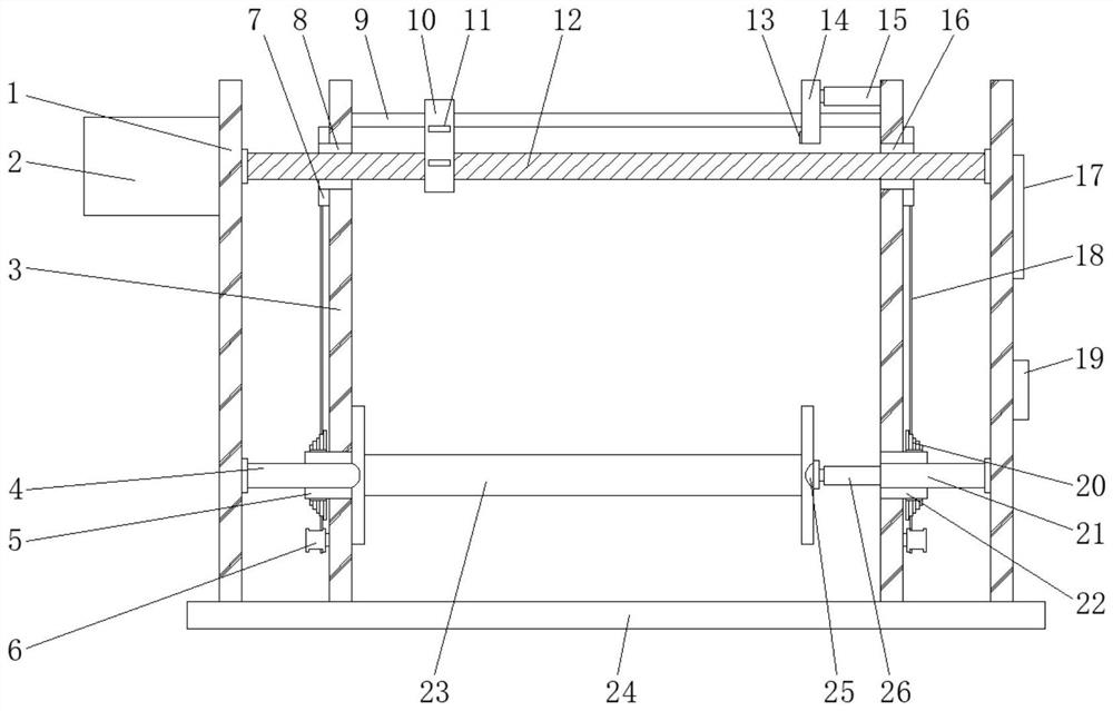
[0024] see Figure 1-2, an embodiment provided by the present invention: a cable winding device, including a pair of main brackets 1, a pair of auxiliary brackets 3, a slider 10, a winding wheel 23 and a base 24, and the two ends of the top of the base 24 are symmetrical A pair of main brackets 1 are fixed, and a pair of auxiliary brackets 3 are symmetrically fixed on the top of the pressure block 25 inside the pair of main brackets 1, and a slide bar 9 is hor...


PUM


Abstract

The invention discloses a cable winding device, comprising a pair of main brackets, a pair of auxiliary brackets, a sliding block, a winding wheel and a base. Two ends of the top of the base are symmetrically fixed with a pair of main brackets, and a pair of auxiliary brackets. The bracket is symmetrically fixed on the inner side of a pair of main brackets, a sliding rod is laterally fixed at the upper end between a pair of the auxiliary brackets, a sliding block 1 is slid on one end of the sliding rod, and a pair of auxiliary brackets below the sliding rod are respectively fixed with The second one-way bearing and the third one-way bearing are provided with a screw rod passing through between the second one-way bearing, the first sliding block and the third one-way bearing. The cable winding device provided by the invention can effectively realize the purpose of driving the whole device by one motor through the cooperation of four one-way bearings and the trapezoidal flywheel group, simplify the device structure, and reduce the production and maintenance costs of the device. , Improve the winding speed, make the length of the cable winding meet the actual winding length of the winding wheel, avoid the phenomenon of hollowing and unevenness of the coil, and improve the overall appearance of the coil.

Description

technical field [0001] The invention relates to the field of cable winding, in particular to a cable winding device. Background technique [0002] The cable is one of the essential parts in the power system. In the production of the cable, the produced cable needs to be reeled, so that the reeled cable can be stored, used and transported quickly. [0003] In the patent application publication number CN 108002115 A, a uniform winding power cable winding device is disclosed, including a base, a support beam, a feed slider, a screw rod, a screw rod, a moving slider, a guide ring, and a touch rod , reversing switch and winding roller, the two feed sliders are respectively sleeved on the outer circumferences of both sides of the screw rod through threaded connection, and the bottom ends of the two feed sliders are fixedly provided with support rods, The inner wall of the bottom end of the two support rods is fixedly equipped with a reversing switch, the moving slider is sleeved ...

Claims


Application Information

Patent Timeline
Patent Type & Authority Patents(China)
IPC IPC(8): B65H54/553B65H54/28B65H57/06B65H54/44B65H59/38
CPCB65H54/2818B65H54/2857B65H54/44B65H54/553B65H57/06B65H59/385B65H2701/34
Inventor 邢军
Owner JINAN SHENGTONG POWER CABLE
Why Eureka
Try Eureka