Inclined support assembling and disassembling device capable of automatically oiling
A technology of oblique support and driving device, which is applied in the direction of injection device, liquid injection device, metal processing, etc., can solve the problems of inability to obliquely support and fix, easy to injure operators, and high physical strength requirements of workers, and achieves good clamping and safe use. and convenient, effort-saving effect
- Summary
- Abstract
- Description
- Claims
- Application Information
AI Technical Summary
Problems solved by technology
Method used
Image
Examples
Embodiment 1
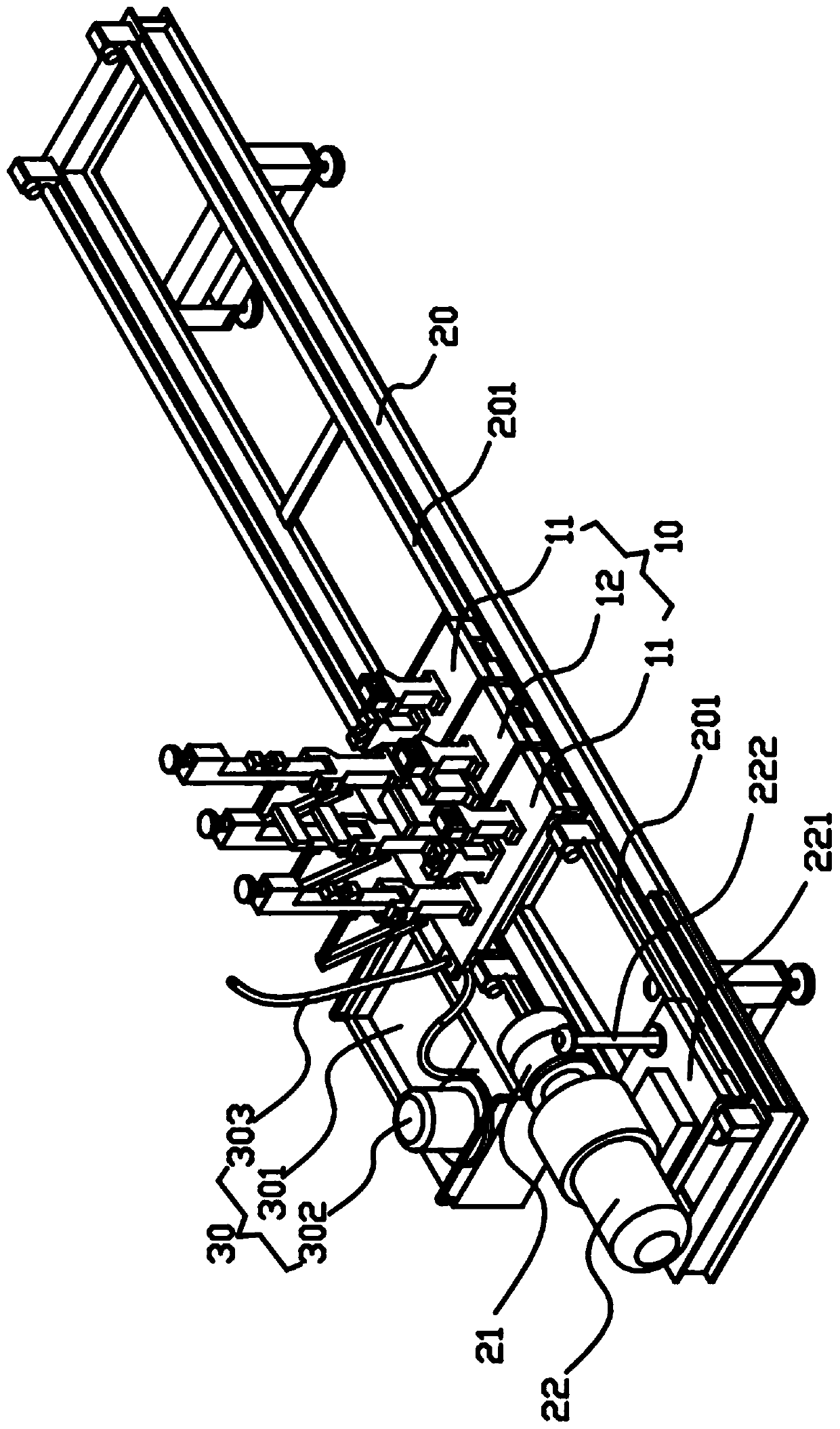
[0037] A self-oiling oblique support disassembly device, such as Figure 6 As shown, the oblique support includes a support rod 1, a screw rod 2, a handle 4 and a connector 3. A hollow cavity is provided in the support rod 1, and two screw rods 2 are threadedly connected with the cavity. The two screw rods 2 are respectively The two ends of the support rod 1 are movably arranged, and one end of the screw rod 2 extends out of the cavity, and a connector 3 is provided on the end of the screw rod 2 extending out of the cavity, wherein the middle part of the support rod 1 is provided with a Two handles 4 are arranged symmetrically and are respectively welded on the outer wall of the support rod 1. This device is used for dismounting or installing the screw rod 2 on the diagonal support.
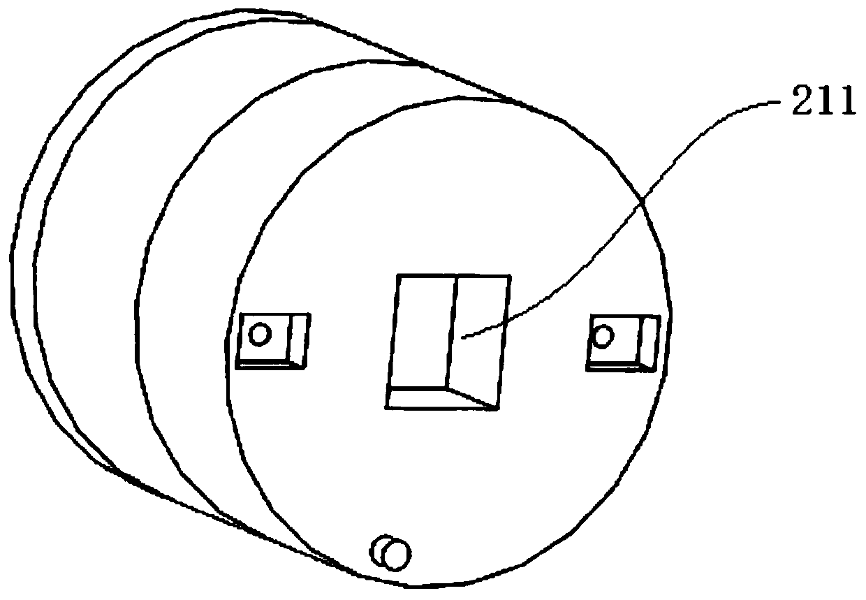
[0038] Such as figure 1 As shown, the device includes an organic base 20, a clamping device 10, a driving device 22, a dismounting head 21 and a refueling device 30, and the clamping device 10 a...
Embodiment 2
[0048] This embodiment is similar to Embodiment 1, the difference is that in this embodiment, both the clamping device 10 and the driving device 22 are movably arranged on the machine base 20, specifically, a linear guide rail 201 is provided on the machine base 20 , the clamping device 10 and the driving device 22 are arranged on the same linear guide rail 201 and both the clamping device 10 and the driving device 22 are slidingly connected with the linear guide rail 201, ensuring that the clamping device 10 and the driving device 22 are located in the same linear direction. The difference from Embodiment 1 or 2 is that in this embodiment, a fixing mechanism needs to be provided on the clamping device 10 or the driving device 22 to limit the movement of the driving device 22 or the clamping device 10 on the linear guide rail 201 , in the process of disassembly or installation, it is necessary to fix the position of either the driving device 22 or the clamping device 10 on the ...
Embodiment 3
[0051] This embodiment is similar to Embodiment 1, except that in this embodiment, the first clamp 11 only includes a first base 113 and a first lower clamping block 112 installed and fixed on the first base 113, wherein the first The top of the lower clamping block 112 is provided with an arc-shaped opening. Since the opening is arc-shaped, when the support rod is placed in the opening, the opening restricts the lateral movement of the support rod. In addition, combined with the second clamp 12 to limit the longitudinal movement and rotational movement of the oblique support, this embodiment The scheme can also play a role in restricting the lateral movement, longitudinal movement and rotational movement of the oblique support.
PUM
 Abstract
Description
Claims
Application Information
 - R&D
- Intellectual Property
- Life Sciences
- Materials
- Tech Scout
- Unparalleled Data Quality
- Higher Quality Content
- 60% Fewer Hallucinations
Browse by: Latest US Patents, China's latest patents, Technical Efficacy Thesaurus, Application Domain, Technology Topic, Popular Technical Reports.
© 2025 PatSnap. All rights reserved.Legal|Privacy policy|Modern Slavery Act Transparency Statement|Sitemap|About US| Contact US: help@patsnap.com


