Rear plate assembly of disc brake block, disc braker and vehicle

A disc brake, disc brake technology, applied in the direction of brake types, brake components, bicycle brakes, etc., can solve the problems of increasing the risk of noise and wear

Inactive Publication Date: 2008-03-12
MERITOR HEAVY VEHICLE BRAKING SYST (UK) LTD
View PDF5 Cites 2 Cited by
  • Summary
  • Abstract
  • Description
  • Claims
  • Application Information

AI Technical Summary

Problems solved by technology

[0008] This arrangement reduces sliding loads but increases the risk of noise and wear due to increased component chatter in use

Method used


Image

  • Rear plate assembly of disc brake block, disc braker and vehicle
  • Rear plate assembly of disc brake block, disc braker and vehicle
  • Rear plate assembly of disc brake block, disc braker and vehicle

Examples


Embodiment Construction

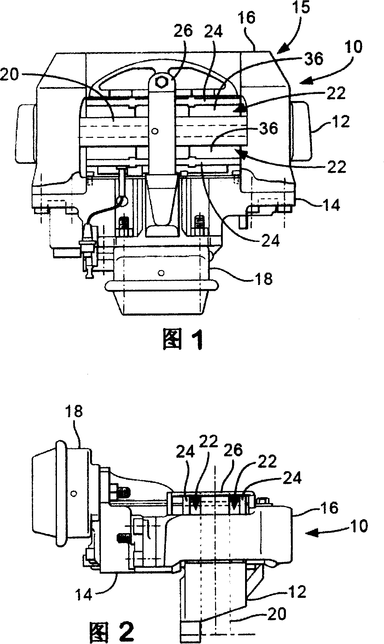
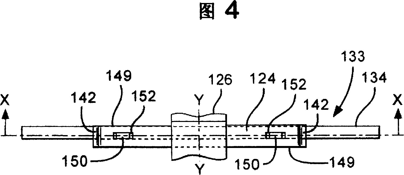
[0019] 4 and 5 illustrate a disc brake pad rear plate assembly 133 according to one embodiment of the present invention. Assembly 133 can be adapted to the prior art disc brake 10 described above. Assembly 133 includes rear plate 134 to which friction material (not shown) is secured. The rear plate includes a pair of circumferentially spaced abutments 140 on a radially outer face 135 . Leaf spring retaining means such as a pair of radially outwardly extending lugs 150 also project from the radially outer face 135 of the rear plate 134 and are positioned between the standoffs 140 .

[0020] As can be seen from FIG. 4 , the leaf spring 124 is an elongated strip having a middle region 148 and an end region 149 . When mounted to the rear plate 134, the leaf springs 124 extend in a circumferential direction transverse to the axis of motion Y-Y of the back and forth movement of the rear plate 134 relative to the rotor 20 in use. The leaf spring is provided with an upturned end 14...


PUM


Abstract

A disc brake pad backplate assembly (133) including a backplate (134) and pad spring (124), the backplate and / or pad spring comprising retaining means (150) to mount the pad spring to the backplate and circumferentially spaced abutments (140) arranged so as to be capable of restraining lateral movement of end portions (142) of the pad spring, the pad spring being dimensioned relative to the spacing of the abutments such that a radially inward loading applied at a central portion (148) of the spring causes the spring to function in a first resilient leaf spring-like mode in which the pad spring end portions are unrestrained up to a predetermined load limit, and such that above the predetermined load limit, the end portions are restrained by the abutments such that the pad spring functions in a second buckling mode, the spring rate being relatively low in the first mode and relatively high in the second mode.

Description

technical field [0001] The invention relates to a disc brake pad rear plate assembly. In particular, the present invention relates to a disc brake pad backplate assembly comprising a backplate and a leaf spring. Background technique [0002] Known disc brakes (shown in Figures 1 to 3) comprise a disc or rotor 20 mounted to the hub for rotation with the wheel. The brake pylon 12 is mounted relative to the axis of rotation of the rotor 20 and is secured to a non-rotating part of the vehicle (eg, the suspension of the vehicle). In a "floating caliper" brake, a brake caliper is slidably mounted on a pylon 12 so as to allow movement parallel to the axis of rotation of the rotor 20 , the brake caliper comprising a beam 16 secured to a housing 14 . The drive mechanism 18 is connected to one or more pistons or tappets (not shown), which are disposed within the housing 14, to apply the force required for the brakes to function. [0003] A pair of brake plates 22 are positioned on ...

Claims


Application Information

Patent Timeline
Patent Type & Authority Patents(China)
IPC IPC(8): F16D65/092F16D55/02B62L1/02B62L3/00F16D65/097
CPCF16D2055/007F16D65/0978F16D65/0977
Inventor 保罗·安东尼·托马斯
Owner MERITOR HEAVY VEHICLE BRAKING SYST (UK) LTD
Why Eureka
Try Eureka