Anti-tipping coil loading and unloading trolley and using method thereof
A technology for trolleys and coils, applied in metal rolling, manufacturing tools, metal processing equipment, etc., can solve problems such as shaking, property loss, and unstable center of gravity, so as to solve the phenomenon of shaking or tipping, reduce the incidence of accidents, flexible action effect
- Summary
- Abstract
- Description
- Claims
- Application Information
AI Technical Summary
Problems solved by technology
Method used
Image
Examples
no. 1 approach
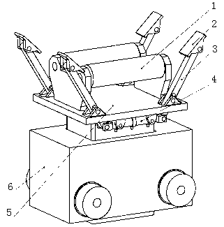
[0029] The first embodiment of the present invention relates to an anti-overturn loading and unloading trolley, such as figure 1 As shown, it includes a hollow trolley body 6, and a lifting base 5 placed in the trolley body 6 and capable of lifting in the vertical direction. The top of the lifting base 5 is fixed with a lifting platform 8 positioned above the trolley body 6, A number of double-rod hydraulic cylinders 4 are arranged below the lifting platform 8, and an idler seat is installed in the upper middle of the lifting platform 8, and two idler rollers 1 are arranged side by side on the idler seat for supporting the coil The lifting platform 8 is also hinged with some clamping devices for clamping the two sides of the coil, and several clamping devices are symmetrically arranged on the axial ends of the idler 1 in groups of two, and each group of clamping devices The lower end passes through the lifting platform 8 and is connected with the piston rod of a double-rod hyd...
no. 2 approach
[0034] This embodiment provides an anti-overturn loading and unloading trolley, such as figure 2 As shown, it includes a hollow trolley body 6, and a lifting base 5 placed in the trolley body 6 and capable of lifting in the vertical direction. The top of the lifting base 5 is fixed with a lifting platform 8 positioned above the trolley body 6, A number of double-rod hydraulic cylinders 4 are arranged below the lifting platform 8, and an idler seat is installed in the upper middle of the lifting platform 8, and two idler rollers 1 are arranged side by side on the idler seat for supporting the coil The lifting platform 8 is also hinged with some clamping devices for clamping the two sides of the coil, and several clamping devices are symmetrically arranged on the axial ends of the idler 1 in groups of two, and each group of clamping devices The lower end passes through the lifting platform 8 and is connected with the piston rod of a double-rod hydraulic cylinder 4; specifically...
no. 3 approach
[0036] On the basis of the above embodiment, further, the lifting platform 8 is also provided with a number of positioning plates 9, the positioning plates 9 are vertically welded to both sides of the connecting rod 3 in pairs, and the positioning plates 9 A pin shaft hole is arranged on the top, and a positioning long hole is provided at the lower end of the connecting rod 3 , and the pin shaft passes through the pin shaft hole and the positioning long hole to hinge the connecting rod 3 between the two positioning plates 9 . It is worth mentioning that the connecting rod 3 can rotate around the pin shaft driven by the double-rod hydraulic cylinder 4, and the pin shaft can move in a small range along the vertical direction of the long positioning hole to ensure that the connecting rod 3 is flexible at the hinge axis. turn.
PUM
 Abstract
Description
Claims
Application Information
 - R&D
- Intellectual Property
- Life Sciences
- Materials
- Tech Scout
- Unparalleled Data Quality
- Higher Quality Content
- 60% Fewer Hallucinations
Browse by: Latest US Patents, China's latest patents, Technical Efficacy Thesaurus, Application Domain, Technology Topic, Popular Technical Reports.
© 2025 PatSnap. All rights reserved.Legal|Privacy policy|Modern Slavery Act Transparency Statement|Sitemap|About US| Contact US: help@patsnap.com


