Waste tinned wire excess material recovery device

A recycling device and tin-plating technology, applied in the direction of electronic waste recycling, recycling technology, circuits, etc., to achieve the effects of improving purity, improving economic benefits, and improving stability

Inactive Publication Date: 2020-03-17
HUBEI UNIV OF TECH
View PDF1 Cites 0 Cited by
  • Summary
  • Abstract
  • Description
  • Claims
  • Application Information

AI Technical Summary

Problems solved by technology

[0004] Based on the technical problem that the existing recycling device can't classify and recycle the three materials of tinned wires well, the present invention proposes a recycling device for waste tinned wires

Method used


Image

  • Waste tinned wire excess material recovery device
  • Waste tinned wire excess material recovery device
  • Waste tinned wire excess material recovery device

Examples


Embodiment 1

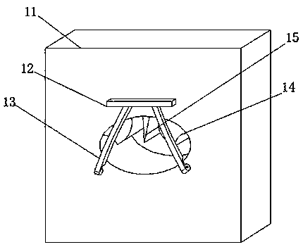
[0026] refer to Figure 1-4 , a waste and old tinned electric wire residue recovery device, comprising a base 1, the top of the base 1 is provided with a rectangular groove, the base 1 is provided with a tin oxide recovery tank 8 at the rectangular groove, and the tin oxide recovery tank 8 is a The bottom end of the side is welded with a pole 2, the tin oxide recovery tank 8 and the top of the pole 2 are welded with an electromagnetic heating chamber 3, the electromagnetic heating chamber 3 is connected to the circuit of the device, and both ends of the electromagnetic heating chamber 3 are equipped with Circular through holes, the inside of the electromagnetic heating chamber 3 is welded with curved grooves 4 at the two circular through holes, the bottom of the electromagnetic heating chamber 3 is provided with a through hole, when tin is converted into tin oxide, the tinned copper The wire is sent into the electromagnetic heating chamber 3 for heating, and the temperature is...

Embodiment 2

[0035] refer to Figure 5 , a recycling device for waste and old tinned electric wires. Compared with Embodiment 1, in this embodiment, in order to improve the stability of the electric wire during peeling, the second fixing plate 11 is positioned on both sides above the circular through hole. Open a rectangular groove, the second fixed plate 11 is welded with a U-shaped bar 25 at the rectangular groove, and the outside of the U-shaped bar 25 is connected with an elastic wheel 24 through the rotation of the shaft. Tightly apply pressure to the wires at all times to prevent the wires from being twisted when they are stripped and improve the stability of the device.

[0036] When in use, when tin is converted into tin oxide, the tinned copper wire is sent into the electromagnetic heating chamber 3 for heating, and the temperature is kept at 140°C. On the discarded tinned copper wire, the inside of the tin layer has not been completely oxidized Tin and stannous oxide react with ...


PUM


Abstract

The invention belongs to the technical field of electrical equipment. The invention relates to a recovery device, in particular to a waste tinned wire excess material recovery device. The technical problem that an existing recycling device cannot well classify and recycle three materials of tinned wires is solved. Presented are solutions, which comprises a base, a rectangular groove is formed in the top end of the base; the base is provided with a tin oxide recovery tank at the rectangular groove; the bottom end of one side of the tin oxide recovery tank is fixedly connected with a strut; electromagnetic heating bins are fixedly connected to the top ends of the tin oxide recovery tank and the supporting rods and connected with a circuit of the device, circular through holes are formed in the two ends of each electromagnetic heating bin, curved grooves are fixedly connected to the positions, at the two circular through holes, in each electromagnetic heating bin, and through holes are formed in the bottom ends of the electromagnetic heating bins. According to the tinned copper wire tinning device, by arranging the electromagnetic heating bin, the tin layer of the tinned copper wire is heated through the heating bin, components in the tin layer are all converted into tin oxide, tin oxide is an important industrial raw material, and economic benefits are brought to recycling work.

Description

technical field [0001] The invention relates to the technical field of electrical equipment design, in particular to a device for recovering waste tinned electric wire residues. Background technique [0002] In the existing technology, the conventional wires are slowly oxidized by the air during use, which may generate a patina, which increases the resistance of the wires and causes adverse effects on heating. Therefore, in the prior art, we use copper wires A layer of tin is plated on the outside to isolate the oxidation of the copper wire by the air, but when recycling this wire, there are three different materials, which cause trouble for recycling. [0003] After retrieval, the Chinese patent application number is CN201710003541.3, which discloses a resource recovery method for waste tinned wires. First, use a cutter to cut the waste tinned wires into 2cm to 3cm strip wires and place them under vacuum stirring heat. Put a grinding ceramic ball with a diameter of 5mm int...

Claims


Application Information

Patent Timeline
Patent Type & Authority Applications(China)
IPC IPC(8): H01B15/00
CPCH01B15/003Y02W30/82
Inventor 汪繁荣周子槊彭禄赵阳张冉
Owner HUBEI UNIV OF TECH
Why Eureka
Try Eureka