
Beam structure form reconstruction method based on optical fiber strain measurement

A technology of optical fiber strain and beam structure, applied in the direction of measuring devices, optical devices, instruments, etc., can solve the problems of not considering the influence of optical fiber measurement, error of reconstruction results, complicated calculation process, etc., and achieve fast calculation speed and low calculation volume Small, the effect of ensuring the calculation speed

Active Publication Date: 2020-03-17
SHANGHAI AEROSPACE CONTROL TECH INST
View PDF7 Cites 4 Cited by
  • Summary
  • Abstract
  • Description
  • Claims
  • Application Information

AI Technical Summary

Problems solved by technology

However, for flexible beam structures with vibrations, the real-time requirements for deformation monitoring are higher, and faster calculation speeds are required. Such methods are often difficult to meet the requirements.
In addition, for a flexible structure with a circular substrate cross-section, multiple optical fibers arranged at circumferential intervals of 90° or 120° are often used to obtain the orthogonal curvature information of the structure, but the torsional deformation of the structure is mostly not considered in the calculation. The influence of optical fiber measurement, which brings certain errors to the reconstruction results; or the calculation process is relatively complicated even though the torsion influence is considered, combined with the characteristics of the reconstruction method itself, the calculation amount is relatively large

Method used


Image

  • Beam structure form reconstruction method based on optical fiber strain measurement
  • Beam structure form reconstruction method based on optical fiber strain measurement
  • Beam structure form reconstruction method based on optical fiber strain measurement

Examples


Embodiment Construction

[0044] The present invention will be further described below through specific embodiments in conjunction with the accompanying drawings. These embodiments are only used to illustrate the present invention, and are not intended to limit the protection scope of the present invention.

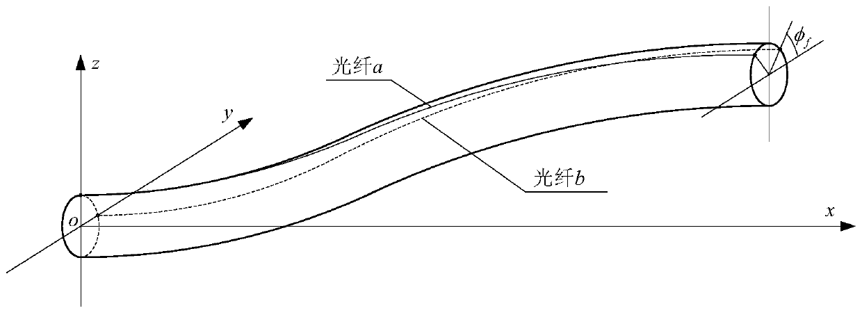
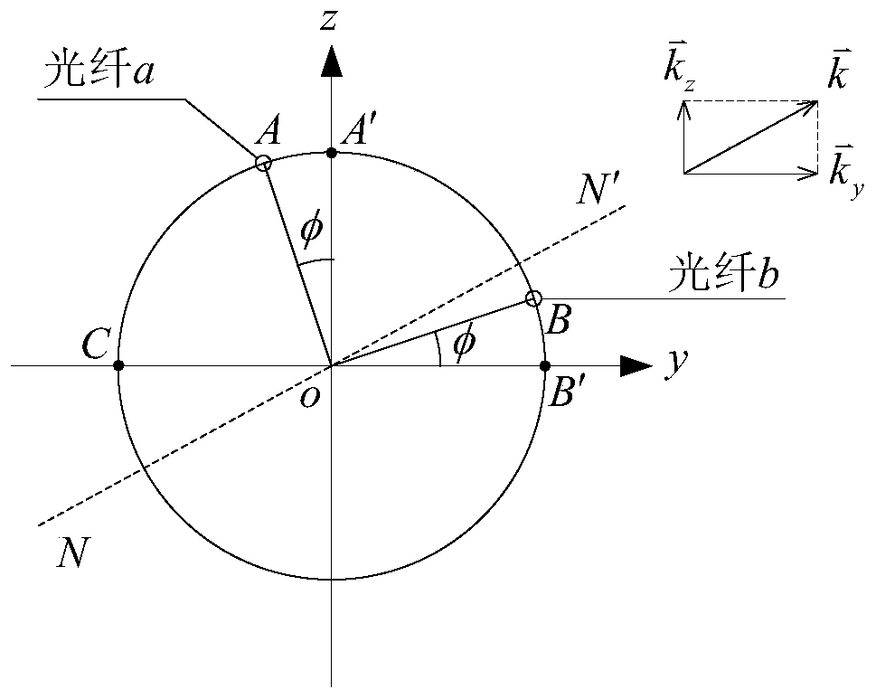
[0045] The present invention proposes a beam structure shape reconstruction method based on optical fiber strain measurement, which is used for static or dynamic three-dimensional shape reconstruction of circular cross-section beam structures under combined deformation of space bending and torsion. Strain information in two orthogonal directions, and at the same time obtain the torsion angle of the beam section through other measurement methods, on this basis, realize the three-dimensional shape reconstruction of the beam according to the strain decomposition and Ko displacement theory; specifically include the following implementation steps:

[0046] Step 1: Use the optical fiber strain sensor pas...


PUM


Abstract

The invention discloses a beam structure form reconstruction method based on optical fiber strain measurement. The method comprises the following steps: step 1, acquiring a section torsion angle of the tail end of a circular-section beam and arranging a plurality of measuring points in an axis direction of the circular-section beam to obtain the surface strain in the axis direction of the beam; step 2, calculating a beam section torsion angle corresponding to each measuring point, and carrying out strain decomposition by combining the surface strains obtained at the measuring points to obtaina surface strain generated by making bending deformation of the beam structure in two orthogonal directions perpendicular to the axial direction; step 3, according to the obtained orthogonal strain information, calculating bending deformation deflections of the beam in the two orthogonal directions respectively based on a Ko displacement theory, thereby completing three-dimensional form reconstruction. Compared with other spatial three-dimensional curve reconstruction methods, the disclosed method considers the influence of torsional deformation and has advantages of high calculation speed andhigh precision under the condition of small deformation.

Description

technical field [0001] The invention relates to the field of deformation measurement and shape reconstruction technology research of flexible structures, in particular to a beam structure shape reconstruction method based on optical fiber strain measurement. Background technique [0002] Deformation measurement and shape reconstruction of flexible structures are important foundations for structural force analysis and vibration control. In aerospace, civil engineering and other fields, the flexible beam structure is a typical structural form. Due to its complex working environment, combined deformation or vibration such as space bending and torsion is very easy to occur, which affects the performance of the entire system. It is of great significance for high-precision deformation measurement and morphological reconstruction. In the measurement, due to its light weight, small size, anti-electromagnetic interference, corrosion resistance, and small impact on the structure, fib...

Claims


Application Information

Patent Timeline
IPC IPC(8): G01B11/16G01B11/24
CPCG01B11/18G01B11/24
Inventor 黄庭轩朱东方刘付成黄静孙俊
Owner SHANGHAI AEROSPACE CONTROL TECH INST
Learn More