
Embedded reinforcing structure and method of bridge expansion device

A technology of expansion device and reinforcement structure, which is applied in the field of pre-embedded reinforcement structure and pre-embedded reinforcement structure of bridge expansion device, which can solve the problems of easy damage, low precision and strength of expansion joint device, fatigue of bridge expansion device, etc. problems, to achieve the effect of increasing steel content, improving anchor strength and installation accuracy, and improving anchor strength

Inactive Publication Date: 2020-03-17
武汉丰瑞桥梁科技有限公司
View PDF5 Cites 0 Cited by
  • Summary
  • Abstract
  • Description
  • Claims
  • Application Information

AI Technical Summary

Problems solved by technology

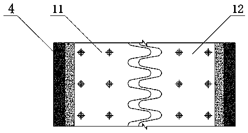
[0005] The purpose of the present invention is to solve the ubiquitous construction defect of the existing expansion joint reserved slot, which will directly cause the bridge expansion device to be easily fatigued and easily damaged. The existing structure and installation and construction methods cannot comprehensively and systematically solve the expansion joint reserved slot The defects and deficiencies of the opening of the expansion joints lead to the low precision and strength of the expansion joint device. Now we provide a reasonable structure, a comprehensive and systematic solution to the construction defects of the reserved slots of the expansion joints, and increase the steel content of the slots of the expansion joints. It improves the anchoring strength, effectively carries out comprehensive and high-precision structural reinforcement to the original pre-embedded structure of the expansion joint notch, and greatly improves the installation accuracy and strength of the expansion joint device. It is a pre-embedded reinforcement structure for bridge expansion devices. and method

Method used


Image

  • Embedded reinforcing structure and method of bridge expansion device
  • Embedded reinforcing structure and method of bridge expansion device
  • Embedded reinforcing structure and method of bridge expansion device

Examples


specific Embodiment approach 1

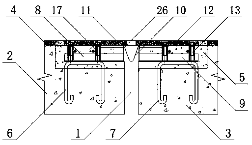
[0065] Specific implementation mode one: see figure 1 , figure 2, the left pre-embedded unit 8 and the right pre-embedded unit 9 include positioning connectors 15 and transverse steel bars 16, and a row of mutually parallel positioning connectors 15 is welded and fixed on the left notch embedded part 6 and the right notch pre-embedded part 7 , the positioning connector 15 is an angle steel, and the positioning connector 15 is vertically fixed with two or more transverse steel bars 16, and the positioning connector 15 is vertically fixed with a slotted nut sleeve 17 or a slotted nut 18, and the slotted nut sleeve Internal threads are provided in the inner hole of the barrel 17 . The position of the long hole nut sleeve 17 or the long hole nut 18 has been accurately positioned in the horizontal and vertical directions, which ensures that the follow-up telescopic device can be installed quickly and accurately, and the installation accuracy is ensured.

specific Embodiment approach 2

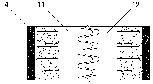
[0066] Specific implementation mode two: see Figure 5 , Image 6 , the left pre-embedded unit 8 and the right pre-embedded unit 9 include positioning connectors 15 and transverse steel bars 16. Compared with the specific embodiment 1, the connection method is different. On the left slot embedded part 6 and the right slot embedded part 7 A row of positioning connectors 15 parallel to each other are respectively welded and fixed. The positioning connectors 15 are angle steels, channel steels or I-beams. The member 15 is perpendicular to the transverse reinforcement 16 . A slotted nut sleeve 17 or a slotted nut 18 is vertically fixed on the positioning connector 15 , and an internal thread is arranged in the inner hole of the slotted nut sleeve 17 . The position of the long hole nut sleeve 17 or the long hole nut 18 has been accurately positioned in the horizontal and vertical directions, which ensures that the follow-up telescopic device can be installed quickly and accuratel...

specific Embodiment approach 3

[0067] Specific implementation mode three: see Figure 5 , Image 6 , the left pre-embedded unit 8 and the right pre-embedded unit 9 include a transverse elongated steel part 19 and a transverse elongated steel part 20, and the left notch embedded part 6 and the right notch pre-embedded part 7 are respectively welded and fixed with two or More than two horizontal long steel pieces 19 are arranged in parallel, and the horizontal long steel pieces 19 are distributed in parallel along the direction of the expansion joint 1, and the horizontal long steel pieces 19 are made of long steel processed parts or steel castings. The steel structure connectors 20 are two and distributed in parallel, and the two transverse elongated steel parts 19 are connected and fixed by a plurality of evenly distributed steel structure connectors 20, and each steel structure connector 20 is fixed with a long hole nut Sleeve 17 or slotted nut 18. The position of the long hole nut sleeve 17 or the long ...


PUM


Abstract

The invention discloses an embedded reinforcing structure and method of a bridge expansion device. The embedded reinforcing structure is characterized in that a left pre-embedded unit, a right pre-embedded unit and an original pre-embedded structure jointly form a high-strength pre-embedded overall new structure; the steel content of the expansion joint notch is increased; the anchor strength is enhanced; the paving compactness defect, the paving flatness defect and the paving gradient defect of the asphalt at the expansion joint notch can be comprehensively overcome; other hidden constructiondefects of the expansion joint notch expansion device can be comprehensively overcome; the left pre-embedded unit and the right pre-embedded unit are machined in a factory or machined through molds on site; high-strength screws or other high-strength fasteners are adopted to be accurately and fixedly connected with anchoring points of different structural forms of the bridge expansion device; andthe anchoring strength and installation precision of the bridge expansion device and the high-precision and high-strength new notch are comprehensively improved, and rapid assembly is achieved, and rapid traffic of roads and bridges is facilitated, and the service life of the bridge expansion device is prolonged, and the driving comfort degree of the bridge expansion device is improved.

Description

technical field [0001] The invention relates to a pre-embedded reinforcement structure and method, in particular to a pre-embedded reinforcement structure and method of a bridge expansion device, belonging to the technical field of bridge engineering construction. Background technique [0002] The bridge expansion device is an important connecting part between the beam ends of the bridge. The quality and performance of the device will directly affect the durability of the entire bridge. Since the bridge expansion device is installed on the weak part of the bridge deck at the beam end, and has been subjected to various natural environmental erosion effects, due to multi-directional displacements such as cold and heat expansion, longitudinal swing, and lateral swing relative torsion during use, That is, three-way displacement, stretching and rotation. Therefore, the overall requirements for the telescopic device include: good waterproof performance, free expansion and contrac...

Claims


Application Information

Patent Timeline
Patent Type & Authority Applications(China)
IPC IPC(8): E01D19/06
CPCE01D19/065
Inventor 刘力源
Owner 武汉丰瑞桥梁科技有限公司
Learn More