Collecting device for biomass fuel

A biomass fuel and collection device technology, applied in the direction of biofuel, waste fuel, fuel, etc., can solve the problems of waste of resources, physical injury of staff, etc., and achieve the effect of convenient unloading work, convenient transportation and use

Inactive Publication Date: 2020-03-13
湖北伟硕生物质能源有限公司
View PDF0 Cites 2 Cited by
  • Summary
  • Abstract
  • Description
  • Claims
  • Application Information

AI Technical Summary

Problems solved by technology

[0003] During the processing of biomass fuel, some materials need to be pulverized and mixed, but a large amount of raw material debris and dust are generated in this process. If these debris and dust are discharged directly, it will not only cause harm to the health of the staff, also waste resources

Method used


Image

  • Collecting device for biomass fuel
  • Collecting device for biomass fuel
  • Collecting device for biomass fuel

Examples


Embodiment 1

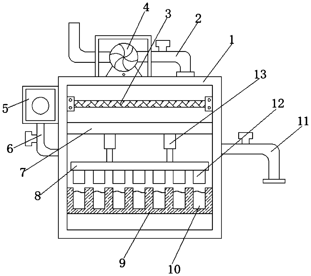
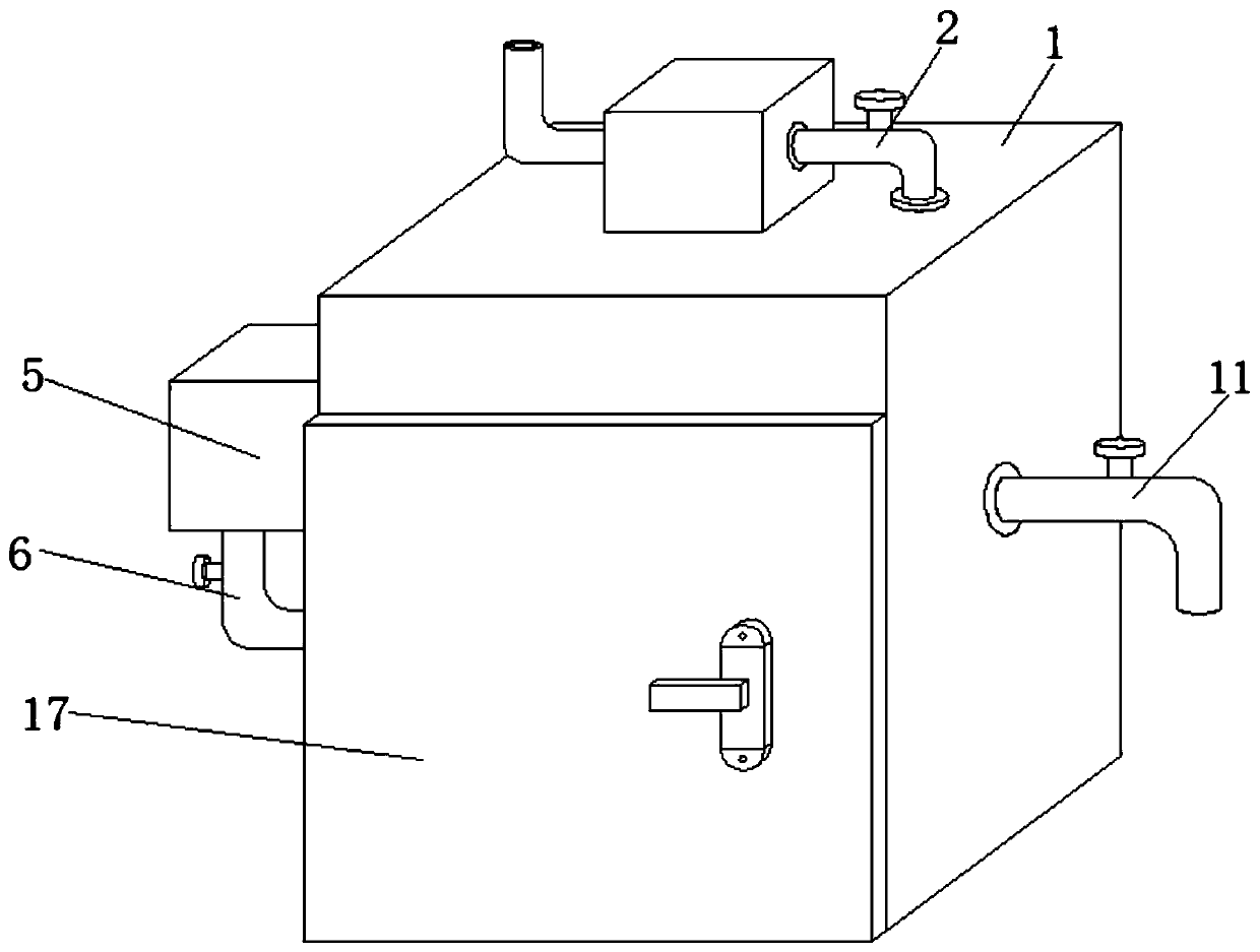
[0025] refer to Figure 1-2 , a collection device for biomass fuel, comprising a box body 1, a connecting pipe 11 is plugged into the outer wall of one side of the box body 1, and an exhaust fan 4 is connected to the top outer wall of the box body 1 by bolts, and one side of the exhaust fan 4 The outer wall is plugged with a suction pipe 2, and the end of the suction pipe 2 away from the exhaust fan 4 extends to the inside of the box body 1, and the inner walls of both sides of the box body 1 are connected with dust filter bags 3 by bolts, and one part of the box body 1 The side outer wall is connected with a hot air blower 5 by bolts, and an air inlet pipe 6 is plugged into one side of the outer wall of the hot air blower 5 , and the end of the air inlet pipe 6 away from the hot air blower 5 extends to the inside of the box body 1 .

[0026] Wherein, the inner walls on both sides of the box body 1 are connected with the fixed rod 7 by bolts, and the bottom outer wall of the f...

Embodiment 2

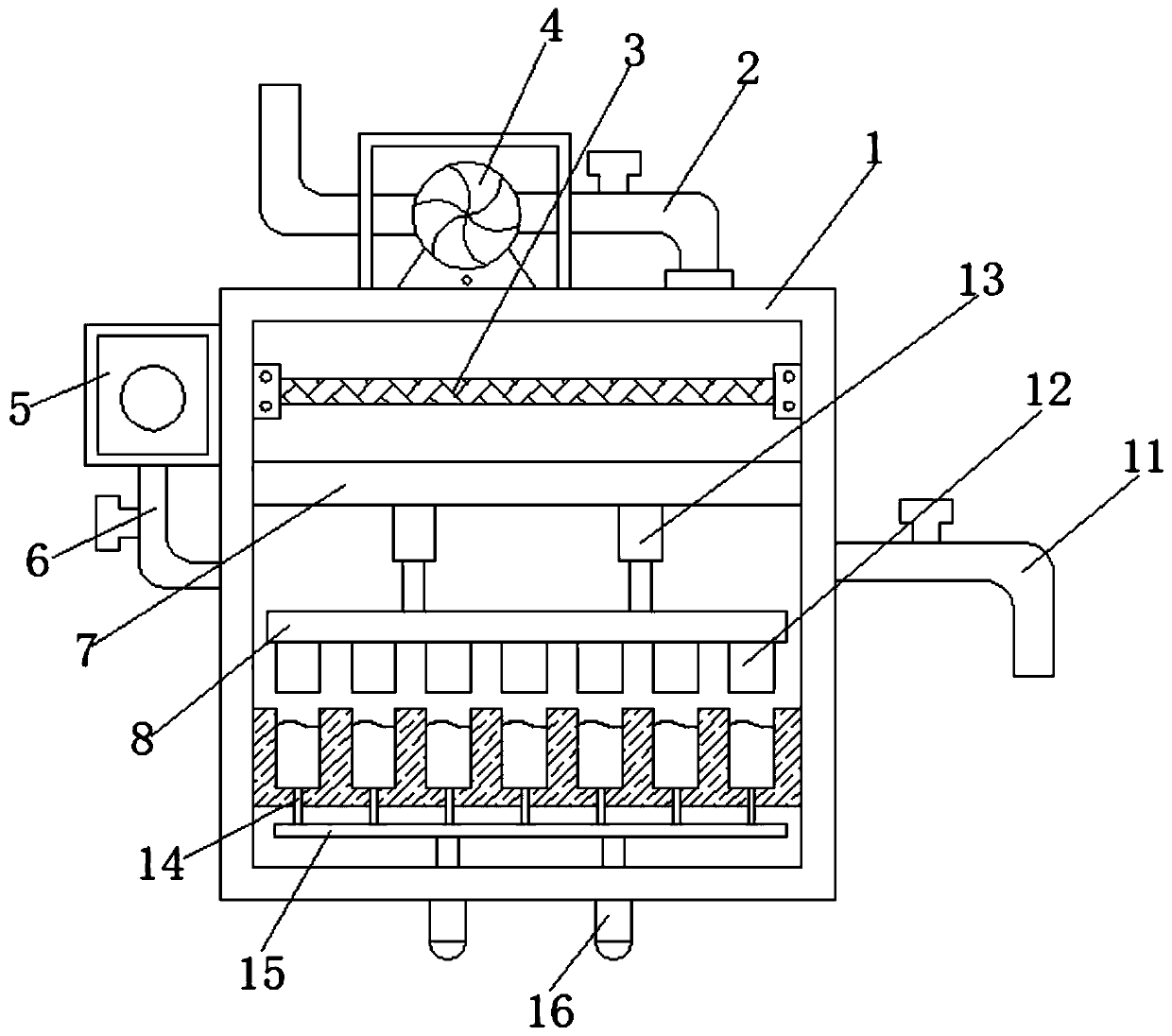
[0029] refer to image 3 , a collection device for biomass fuel. Compared with Embodiment 1, the outer wall of the bottom of the box body 1 is inserted with a second electric push rod 16, and one end of the outer wall of the second electric push rod 16 is connected by bolts. The second connecting rod 15, the top outer wall of the second connecting rod 15 is welded with a fixing column 14, and the bottom outer wall of the pressure groove 10 has a circular hole, and one end of the fixing column 14 extends into the circular hole.

[0030] Working principle: When in use, the staff inserts the connecting pipe 11 into the pulverizer, and then starts the exhaust fan 4, and the exhaust fan 4 can suck the debris generated during the crushing process into the box body 1 through the connecting pipe 11, which can effectively The debris is collected to avoid the direct discharge of the debris and cause harm to the body of the staff. When the debris collected in the box 1 falls into the pre...


PUM


Abstract

The invention discloses a collecting device for biomass fuel. The collecting device comprises a box body; a connecting pipe is inserted into an outer wall of one side of the box body; an exhaust fan is arranged on an outer wall of the top of the box body; an air suction pipe is inserted in an outer wall of one side of the exhaust fan; one end, far away from the exhaust fan, of the air suction pipeextends into the box body; inner walls of two sides of the box body are provided with a dust removing filter bag; a hot air fan is arranged on an outer wall of one side of the box body; an air inletpipe is inserted into an outer wall of one side of the hot air fan; one end, far away from the hot air fan, of the air inlet pipe extends into the box body; inner walls of two sides of the box body are provided with a fixing rod. According to the invention, after the chips collected in the box body fall into a pressing groove, a first electric push rod is started, and a pressing block is driven bythe first electric push rod to move downwards to extruding and molding the chips; and meanwhile, after the chips are extruded and molded, the chips can be dried by the hot air fan, so that later transportation and use by people are facilitated.

Description

technical field [0001] The invention relates to the technical field of biomass fuels, in particular to a collection device for biomass fuels. Background technique [0002] Biomass fuel refers to the burning of biomass materials as fuel, generally mainly agricultural and forestry waste (such as straw, sawdust, bagasse, rice bran, etc.), which is mainly different from fossil fuels. In the current national policy and environmental protection standards, direct combustion of biomass is a highly polluting fuel, which is only used in large stoves in rural areas and is not allowed to be used in cities. The application of biomass fuel is actually mainly biomass briquette fuel, which uses agricultural and forestry waste as raw materials, and is made into various shapes (such as lumps, granules, etc.) through crushing, mixing, extrusion, drying and other processes. A new type of clean fuel that can be directly burned. [0003] During the processing of biomass fuel, some materials nee...

Claims


Application Information

Patent Timeline
Patent Type & Authority Applications(China)
IPC IPC(8): B02C23/00B30B11/04B01D46/02C10L5/44C10L5/48F26B21/00
CPCB01D46/02B02C23/00B30B11/04C10L5/445C10L5/48C10L2200/0469F26B21/001Y02E50/10Y02E50/30
Inventor 谢信春
Owner 湖北伟硕生物质能源有限公司
Why Eureka
Try Eureka