Laser Interferometer Receiver
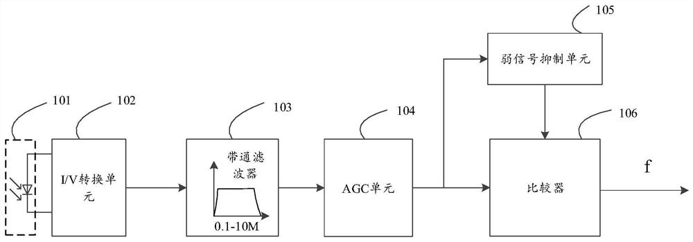
A laser interferometer and receiver technology, applied in the field of measurement, can solve the problems of reduced measurement efficiency and measurement accuracy, inability to realize multi-channel multiplexing function, and single measurement optical path channel, so as to improve measurement efficiency and measurement accuracy, and improve measurement accuracy. Accuracy and measurement efficiency, the effect of improving the signal-to-noise ratio
- Summary
- Abstract
- Description
- Claims
- Application Information
AI Technical Summary
Problems solved by technology
Method used
Image
Examples
Embodiment 1
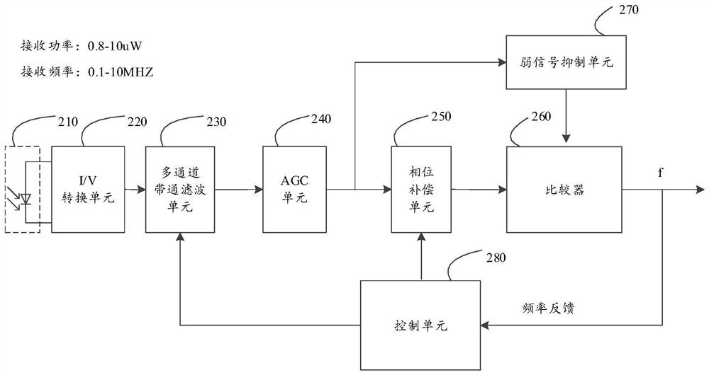
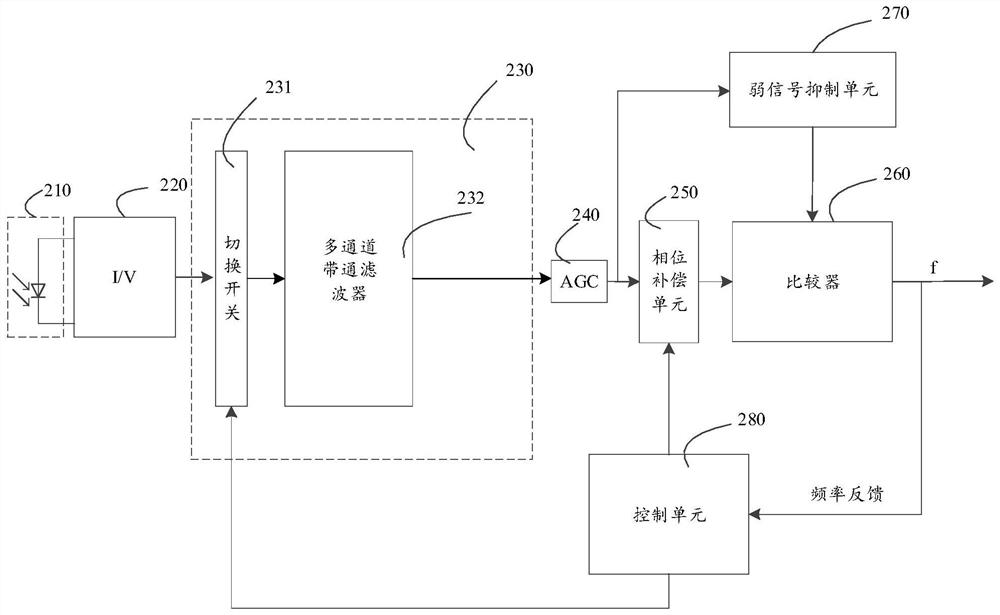
[0043] Please refer to Figure 2 to Figure 5 , the laser interferometer receiver provided by Embodiment 1 of the present invention includes a photoelectric detection unit 210, an I / V conversion unit 220, a multi-channel bandpass filter unit 230, an AGC unit 240, a phase compensation unit 250, a comparator 260, a weak signal suppression unit 270 and control unit 280 .
[0044] Wherein, the photoelectric detection unit 210 is used to detect the interference light signal sent by the laser interferometer and convert it into an analog current signal. The photodetection unit 210 may be a photodiode.
[0045] Please refer to Figure 2 to Figure 4 , the I / V conversion unit 220, configured to convert the analog current signal converted by the photodetection unit 210 into an analog voltage signal.
[0046] Please refer to Figure 2 to Figure 4 , a multi-channel band-pass filter unit 230, configured to select a certain channel of a sub-frequency bandwidth of a narrower frequency rang...
Embodiment 2
[0064] Please refer to Figure 6 , Embodiment 2 of the present invention is improved on the basis of Embodiment 1. The difference is that the multi-channel bandpass filtering unit 230 may also include a summation unit 233, which is used to select a selected channel band The pass filter 232 and a certain channel band-pass filter 232 that is closed at the same time are superimposed and summed to ensure the accuracy of the sum signal obtained, avoiding the noise of the multi-channel band-pass filter unit 230 when the channel is switched, thereby improving the measurement efficiency. efficiency and measurement accuracy. That is, the summation unit 233 can smoothly realize transition switching between channels. The summation unit 233 may employ an adder.
Embodiment 3
[0066] Please refer to figure 2 and Figure 7 , the third embodiment of the present invention is improved on the basis of the first embodiment, the difference is that the multi-channel band-pass filter unit 230 is an adjustable band-pass filter 234 . For example: the overall frequency bandwidth of the adjustable bandpass filter 234 is 0.1-10 MHz, and the adjustable bandpass filter 234 can be adjusted to several sub-frequency bandwidths within the frequency bandwidth of 0.1-10 MHz.
[0067] Please refer to Figure 8 and Figure 9 , the adjustable bandpass filter 234 of the third embodiment of the present invention adopts an LC resonant filter with adjustable frequency bandwidth formed by parallel connection of the inductor L1 and the varactor diode VD1 . At this time, the varactor diode VD1 is used in reverse connection.
[0068] The working principle of the third embodiment of the present invention is basically the same as that of the first embodiment, the difference lies...
PUM
 Abstract
Description
Claims
Application Information
 - Generate Ideas
- Intellectual Property
- Life Sciences
- Materials
- Tech Scout
- Unparalleled Data Quality
- Higher Quality Content
- 60% Fewer Hallucinations
Browse by: Latest US Patents, China's latest patents, Technical Efficacy Thesaurus, Application Domain, Technology Topic, Popular Technical Reports.
© 2025 PatSnap. All rights reserved.Legal|Privacy policy|Modern Slavery Act Transparency Statement|Sitemap|About US| Contact US: help@patsnap.com


